Pro i/o module operation guide – RED PRO I/O MODULE User Manual
Page 5
COPYRIGHT © 2012 RED.COM, INC
/
955-0010, Rev-B 5
PRO I/O MODULE
OPERATION GUIDE
DIGITAL AUDIO INPUT (AES)
• 2 or 4 channels of 24-bit, nominal 48KHz AES digi-
tal audio
• SMPTE 12M Timecode Output
• Pins 2 & 3 replace the analog audio inputs 1 & 2
• Pins 5 & 6 replace the analog audio input 3 & 4
Note: Audio samples in the range of 32-96KHz are
supported, but will be re-synchronized to 48KHz.
LEMO EAG.1B.307.CLN
Facing PRO I/O MODULE
PIN
DESCRIPTION
1
Ground A
2
Line A (+)
3
Line A (-)
4
Ground B
5
Line B (+)
6
Line B (-)
7
SMPTE 12 M Time Code Out
LEMO EAG.0B.304.CLN
Facing PRO I/O MODULE
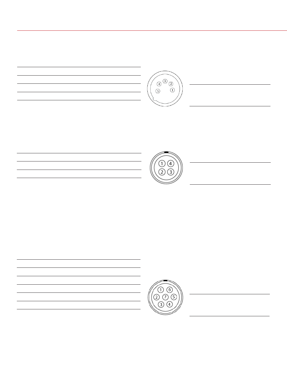
AUXILIARY POWER OUTPUT (PWR)
• Supplies unregulated (+) 11.5 to 17V battery pass-
through power between pins 1 and 4
• Maximum sustained current draw: 1.5 Amp
PIN
DESCRIPTION
1
Camera Ground
2
Not Used
3
Not Used
4
(+) 9-17V unregulated battery loop through output
5-PIN XLR
Facing PRO I/O MODULE
AUDIO OUTPUT (OUT)
• A 5-pin XLR connector supports two chan
nels of balanced analog audio output
PIN
DESCRIPTION
1
(+) Line output, left channel
2
Camera Ground
3
(-) Line output, left channel
4
(+) Line output, right channel
5
(-) Line output, right channel