Middle marker sense, Adjustments, Mb10 pin assignments – PS Engineering MB-10 Installation Manual User Manual
Page 7: Unit installation, Panel installation, Iddle, Arker, Ense, Djustments, Mb10
PS Engineering
MB10 Marker Beacon Receiver
Installation and Operator’s Manual
200-023-0001
Page 2-3
Rev. 9, Sept. 2013
2.4.7
Middle Marker Sense
A Middle Marker Sense output signal is available from the MB10 to flight control systems. This function
will not operate during the test mode. This output will go to +4.5 VDC ( 1.0 VDC) when a valid Middle
Marker signal is received. This output is J1, pin 5.
2.5
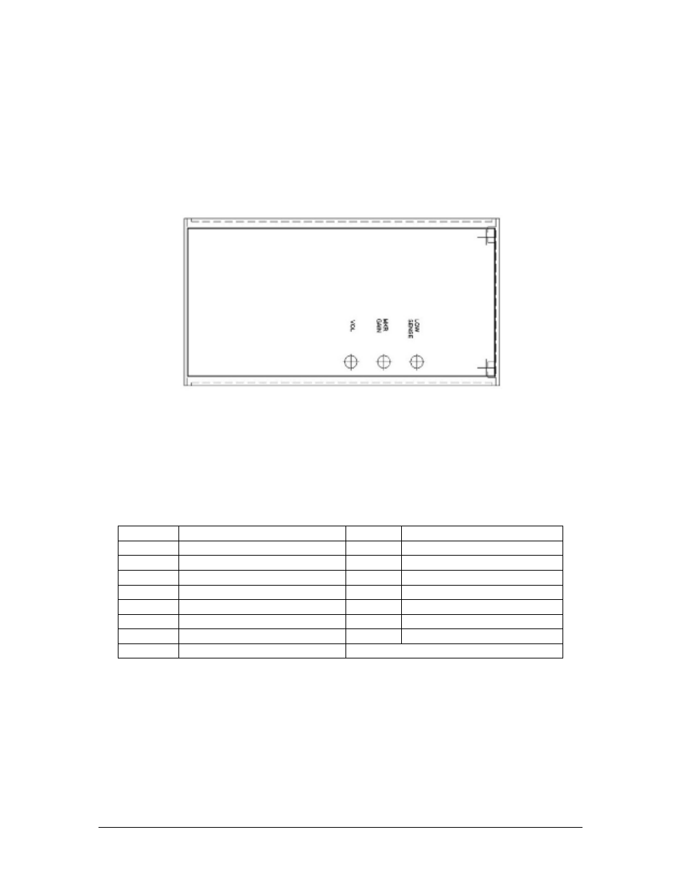
Adjustments
The MB10 is factory adjusted to accommodate the typical requirements for most aircraft configurations.
There are three adjustments in the top cover that allow the installer to tailor the specific functions.
Figure 2-1 MB10 adjustment Locations
Marker Beacon Volume, turn adjustment counterclockwise to increase marker beacon audio
level.
MKR Gain- Set for High sensitivity level
LOW SENSE, Sets low sensitivity
2.6
MB10 Pin assignments
J10
Function
J10
Function
1
14/28 VDC Aircraft Power
9
Aircraft Ground
2
White Lamp Output Active High
10
White Lamp Output Active Lo
3
Amber Lamp Output Active High
11
Amber Lamp Output Active Lo
4
Blue Lamp Output Active High
12
Blue Lamp Output Active Lo
5
MM Sense Output
13
Remote Test/Mute
6
Marker Audio Output
14
Marker Audio Ground
7
14 V lighting Input
15
Remote High Sense Mode
8
28 V lighting Input
2.7
Unit Installation
2.7.1
Panel Installation
The MB10 panel mount is installed from the back of the panel. After the holes are drilled, carefully feed
the lamps and their wires through the lamp holes. Then secure the unit to the panel with the two #4-40
screws through the front plate, instrument panel, and into the unit.
Then, press the lamps into their respective openings on the front plate, until tight. They are flared to press
fit into the chassis.