6equipment supplied, 7equipment required but not supplied, 8license requirements – PS Engineering MB-10 Installation Manual User Manual
Page 4: Equipment, Supplied -2, Required, License, Requirements -2, 6 equipment supplied, 7 equipment required but not supplied
PS Engineering
MB10 Marker Beacon Receiver
Installation and Operator’s Manual
200-023-0001
Page 1-2
Rev. 9, Sept. 2013
MARKER BEACON RECEIVER:
Frequency:
75 MHz Crystal Controlled
Sensitivity:
Low:
High:
Capable of: (preset at factory for field application)
1000 Volts (Hard) (360 to 570 V soft)
200 Volts (Hard) (130 to 200 V soft)
Selectivity:
-6 dB at ±10 kHz
-40 dB at ±120 kHz
External Lamp Output:
7.5 (±4 VDC unloaded, at maximum brightness) VDC
positive when active, max. current 125 mA per lamp out-
put
MM Sense:
Active high (4.5 ± 1.0VDC)
Output impedance:
510
Audio Output:
38 mW <5% THD typical
1.6
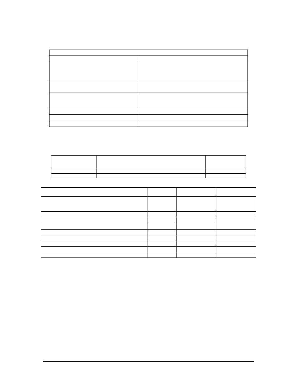
EQUIPMENT SUPPLIED
1 ea. of the following units:
Model
Description
Part Number
MB10
MB10 Marker Beacon Receiver and Indicator.
050-023-0100
MB10R
MB10 Marker Beacon Receiver (remote)
050-023-0101
MB10 Installation Kits:
250-023-0100
250-023-0101
Description
Quantity
Part
Number
Part
Number
DB-15 Female Connector, Solder
1
425-016-0001
425-016-0001
DB-15 Back shell, Plastic
1
425-015-0003
425-015-0003
Screw, Philips, #4-40 x 3/8” Black
2
475-442-0002
Faceplate, MB10 Horizontal
1
575-023-0000
Faceplate, MB10 Vertical
1
575-023-0001
Remote Switch
1
731-004-0005
Sub- D connector Thumb screws
2
475-002-0002
475-002-0002
Mounting Flange
2
430-023-0030
1.7
EQUIPMENT REQUIRED BUT NOT SUPPLIED
a. Circuit Breaker: 1.0 amp
b. Marker Antenna (75 MHz, VSWR 1.5:1, and appropriate for the airspeed) with 50 Ω coax
(RG-58C/U or equiv.)
c. Interconnect Wiring
1.8
LICENSE REQUIREMENTS
None