Marker beacon installation, Marker antenna installation, External marker lights – PS Engineering PMA8000D Installation Manual User Manual
Page 18: Middle marker sense, Marker sensitivity switch (j2 pin 13), Adjustments
PS Engineering
PMA8000D Audio Selector Panel and Intercom System
Installation and Operator’s Manual
200-890-0304
Page 2-10
Rev. 6, Oct. 2014
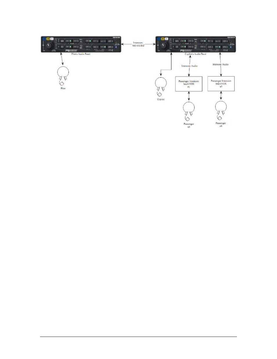
Figure 2-3 Audio Panel Configuration with Expansion
2.6
Marker Beacon Installation
2.6.1
Marker Antenna Installation
A marker beacon antenna, appropriate to the type and speed of the aircraft, is required (not included). Refer
to aircraft and antenna manufacturer's installation instructions, as well as AC43.13-2B (or later revision),
Chapter 3, for information on proper antenna installation techniques. The marker beacon antenna must be
mounted on the bottom of the aircraft.
2.6.2
External Marker Lights
For installations that require external marker beacon lights, there are three outputs that can drive 12-Volt
lamps only. The external output lamps are driven high (typically +7.0 VDC
4.0 VDC unloaded, at MAX
brightness) when active. Maximum source current per lamp is 125 mA. Voltage varies with photocell dim-
ming.
2.6.3
Middle Marker Sense
A Middle Marker Sense output signal is available from the PMA8000 to certain flight control systems. This
function will not operate during the test mode. This output will go to +4.5 VDC (
1.0 VDC) when a valid
Middle Marker signal is received. This output is J1, pin 39.
2.6.4
Marker Sensitivity switch (J2 Pin 13)
The PMA8000D defaults to LOW marker sensitivity of 1000µVolts. If High marker beacon sensitivity is
desired, J2 Pin 13 can be connected to ground (or J2 pin 14), through a switch, to set the marker beacon
threshold sensitivity to 200 µVolts.
2.7
Adjustments
The PMA8000D is factory adjusted to accommodate the typical requirements for most aircraft configura-
tions. There are three adjustments in the top cover that allow the installer to tailor the specific functions.