Potter EVD-2 User Manual
Page 7
7
EVD-2 • 5401042 • REV N • 6/09
EVD-M Terminal Connections
Terminal Terminal
Description
No.
Name
1
(+)
Power Supply Connection, +12 VDC, nominal (See note 1)
2
(-)
Power Supply Connection, 0 VDC (See note 1)
3
SPARE
Spare Terminal Block Position
4
SHIELD
Remote Pickup Cable Shield Connection or End of Line Resistor
(See note 2)
5
SIGNAL
Remote Pickup Sensor Signal or End of Line Resistor (See note 2)
6
REF
Remote Pickup Reference Signal or End of Line Resistor (See note 2)
7
RTN
Accessory Return Connection (See note 3)
8
TEST
Accessory Remote Test Input, Connect to RTN to Activate Test
(See note 3)
9
ALARM
Accessory Remote Annunciator, Alarm (See notes 3, 4)
10
TAMPER
Accessory Remote Annunciator, Tamper (See notes 3, 5)
11
COM
Tamper Alarm Contact, Common
12
NC
Tamper Alarm Contact, Normally Closed in NON-TAMPER STATE
13
NC
Alarm Relay Contact, Normally Closed in NON-ALARM STATE
14
COM
Alarm Relay Contact, Common
15
NO
Alarm Relay Contact, Normally Open in NON-ALARM STATE
Notes
1.
Observe polarity of power supply connections. Application of voltages greater than 18 VDC may result in damage to unit.
2.
If EVD-R remote pickups are installed, remove the factory installed, 10K Ohm, 1% end of line resistors from pins 4-5 and pins 5-6. See
Figures 2a and 4 for details.
3.
Connections to optional RTA, Remote Test Annunciator, or dry contacts from any UL listed central station test unit. See Figure 5 for details.
4.
Remote annunciator terminal provides power-limited +12 VDC when alarm contact is in its ALARM state. Limit current draw to 10mA.
5.
Remote annunciator terminal provides power-limited +12 VDC when tamper alarm contact is in its TAMPER state.
Limit current draw to 10mA.
6.
Pins 1-15 are power limited.
EVD-R Remote Pickup
The EVD-R remote pickup detects attack vibrations with the same vibration sensing components as the internal pickup on the EVD-M
controller. The EVD-R amplifi es and transmits these vibrations to the EVD-M controller.
A cover tamper and a back tamper protect the EVD-R from cover removal or prying. If either of these tampers activate or the tamper from the
safe contact interface activates, the EVD-R will signal a tamper condition to the EVD-M. During a tamper condition, the EVD-R network is
fully capable of signaling alarm conditions to the EVD-M controller. If more than fi ve EVD-R remote pickups simultaneously signal tamper to
the EVD-M controller, the EVD-M will signal an alarm.
The EVD-R contains a magnetically activated test switch that permits testing of each EVD-R in the remote pickup network. The EVD-R
provides terminals for the connection of dry contacts from any Underwriters Laboratories listed safe contact.
Refer to Figure 3 for key component locations and terminal descriptions.
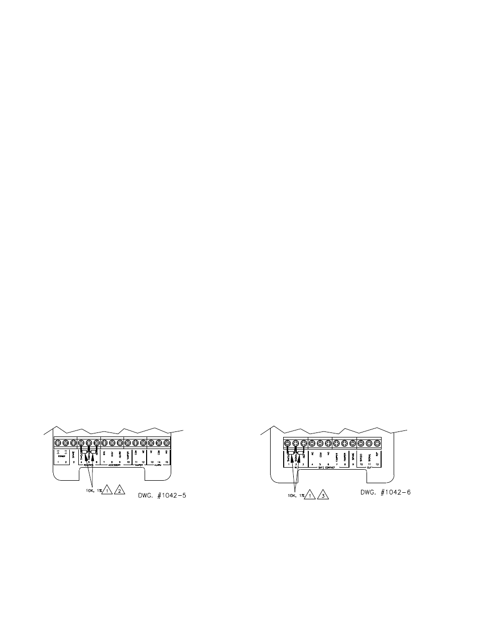
Figure 2. End Of Line Resistor Locations
(a)
(b)
EVD-M
EVD-R
Notes
1.
Be sure that end of line resistor leads do not make contact with other connections.
2.
If any EVD-R remote pickups are connected, remove end of line resistors. (Refer to Figure 4.)
3.
If the OUT terminals of another EVD-R are wired to the IN terminals of an EVD-R, remove the factory installed end of line resistors on the
EVD-R. (Refer to Figure 4.)