Power supply - mains, Control connections – OmniSistem PR Pilot 575 User Manual
Page 5
Pilot 575 Manual_ Last Revision_En.doc
5/22
Connect the power cord as follows:
L (live) =brown
E (earth) =yellow/green
N (neutral) =blue
Use the plug provided to connect the mains power to the projector paying attention to the voltage and
frequency marked on the panel of the projector. It is recommended that each projector be supplied
separately so that they may be individually switched on and off.
IMPORTANT
It is essential that each projector is correctly earthed and the electrical installation conforms to
all relevant standards. Power consumption of the PILOT 575 is 780W.
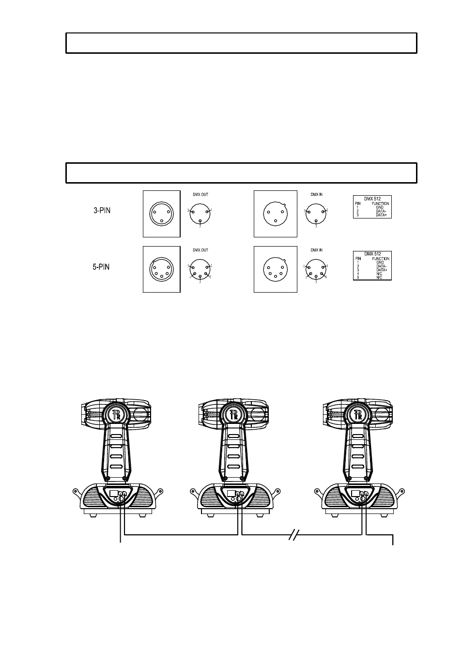
Connection between controller and projector and between one projector and another must be made
with 2 core-screened cable, with each core having at least a 0.5mm diameter. Connection to and from
the projector is via cannon 3 pin (which are included with the projector) or 5 pin XLR plugs and sockets.
The XLR's are connected as shown in the figure above.
Note: care should be taken to ensure that none of the pins touch the metallic body of the plug or each
other. The body of the plug is not connected in any way. The PILOT 575 accepts digital control signals
in protocol DMX512 (1990).
Connect the controller’
s output to the first fixture’
s input, and connect the first fixture’
s output to the
second fixture’
s input and connect the rest fixtures in the same way. Eventually connect the last
fixture’
s output to a DMX terminator as shown in the figure below.
DMX OUT
DMX IN
DMX OUT
DMX IN
TERMINATOR
DMX IN FROM
CONTROLLER
DMX IN
DMX OUT
POWER SUPPLY - MAINS
CONTROL CONNECTIONS