Controller mode - dmx operation – OmniSistem PR Pilot 250 Wash User Manual
Page 7
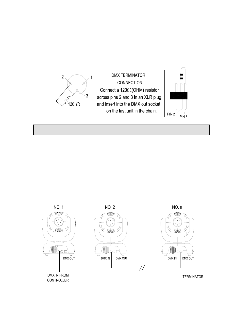
DMX TERMINATOR
In the Controller mode, the DMX output has to be connected with a DMX terminator at the last fixture
in the chain. This prevents electrical noise from disturbing and corrupting the DMX control signals.
The DMX terminator is simply an XLR connector with a 120
Ω (ohm) resistor connected across pins 2
and 3, which is then plugged into the output socket on the last projector in the chain. The connections
are illustrated above.
CONTROLLER MODE - DMX OPERATION
Each PILOT WASH must be given a DMX start address so that the correct projector responds to the
correct control signals. This DMX start address is the channel number from which the projector starts
to “listen” to the digital control information being sent out from the controller. The PILOT WASH has 10
channels, so set the No. 1 projector’s address 001, No. 2 projector’s address 011, No. 3 projector’s
address 021, No. 4 projector’s address 031, and so on.
Certainly, you may use formulation: address = channels x (projector No. –1) +1
For example, for the No. 4 projector’s start address, you should calculate according to formulation: 10
x (4 – 1) +1 = 31, so you set the No. 4 projector start address 031. (How to set DMX start address
please refer to “Operation” section.)
Connect the controller’s output to the first fixture’s input, and connect the first fixture’s output to the
second fixture’s input. The rest may be deduced by analogy. Eventually connect the last fixture’s
output to a DMX terminator as shown in the figure below.
When a DMX 512 signal is received the LED will illuminate green. When not receiving a DMX signal
the green and red LEDs will be off.
Pilot Wash manual.doc
7/12