Xlr connectors and terminator – OmniSistem PR Pilot 250 Wash User Manual
Page 6
SETUP OPTIONS
CODE CHOICE
FUNCTION
Y
Tilt inversion enable-Tilt is inverted
1
N
Tilt inversion disable-Tilt is normal
Y
Pan inversion enable-Pan is inverted
2
N
Pan inversion disable-Pan is normal
3
Not
used
Y
Automatic programmes (effect 1) enable
5
N
Automatic programmes (effect 1) disable
4
5
Y
Y
Automatic programmes (effect 2) enable
4
5
N
Y or N
Automatic programmes (effect 2) disable
Y
16bit Pan/Tilt movement resolution enable
6
N
16bit Pan/Tilt movement resolution disable
7
Not
used
8
Not
used
STAND-ALONE MODE
For Stand-Alone operation enable a combination of options 4 and 5.
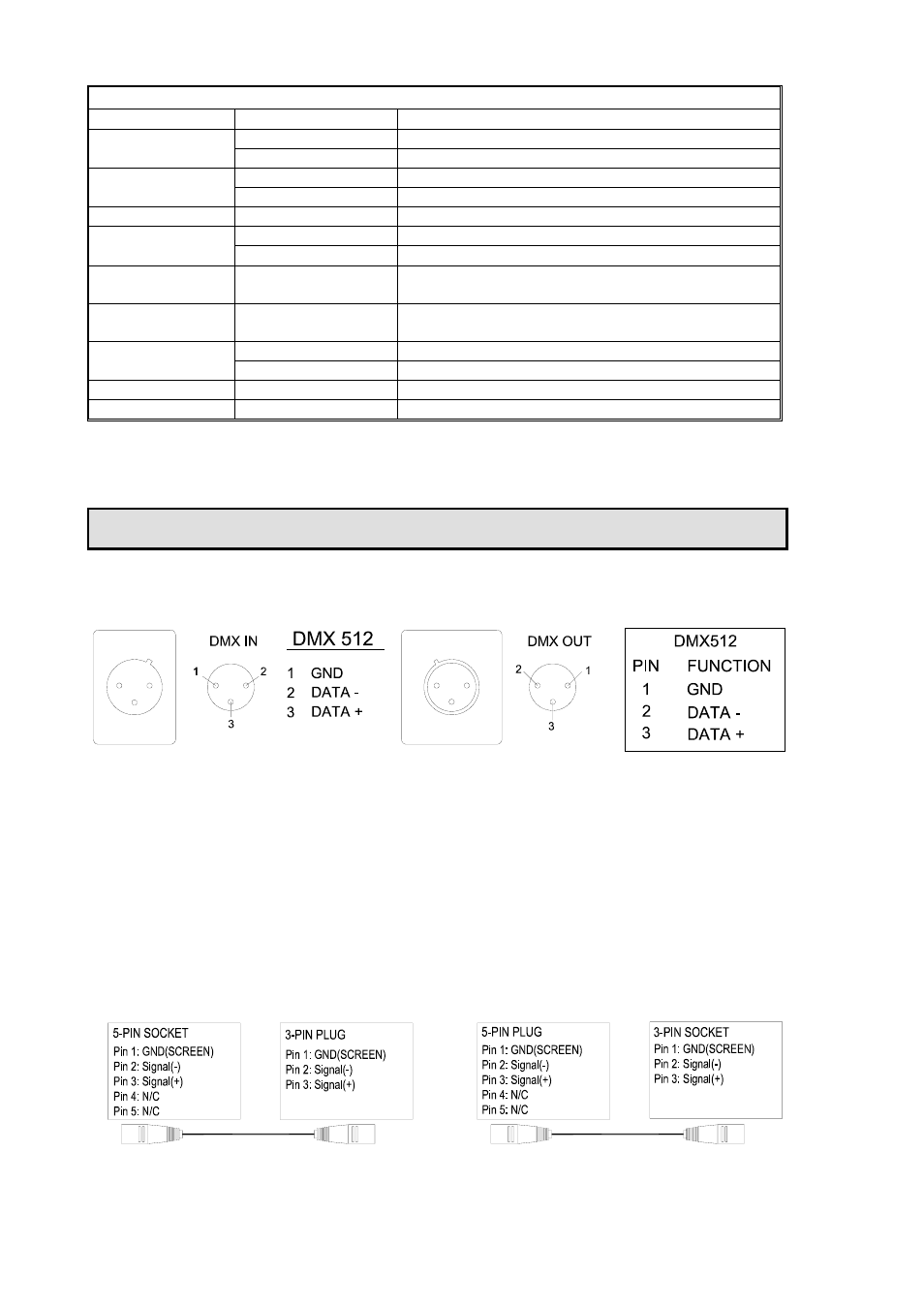
XLR CONNECTORS
Connection between controller and projector and between one projector and another must be made
with 2 core screened cable, with each core having at least a 0.5mm diameter. Connection to and from
the projector is via cannon 3 pin XLR plugs and sockets which are included with the projector. The
XLR's are connected as shown in the table above.
Note, care should be taken to ensure that none of the connections touch the body of the plug or each
other. The body of the plug is not connected in any way. The PILOT WASH accepts digital control
signals in standard DMX512 (1990) format.
XLR CONNECTORS AND TERMINATOR
Pilot Wash manual.doc
6/12
5-PIN AND 3-PIN CONVERSION
PILOT WASH uses 3-pin XLR plug / socket. If your controller uses 5-pin XLR plug / socket, you should
convert 5-pin plug / socket into 3-pin socket / plug as shown below.