Power supply – mains, Control connections, Important – OmniSistem PR Pilot 150 User Manual
Page 5: L = brown e = green/yellow n = blue
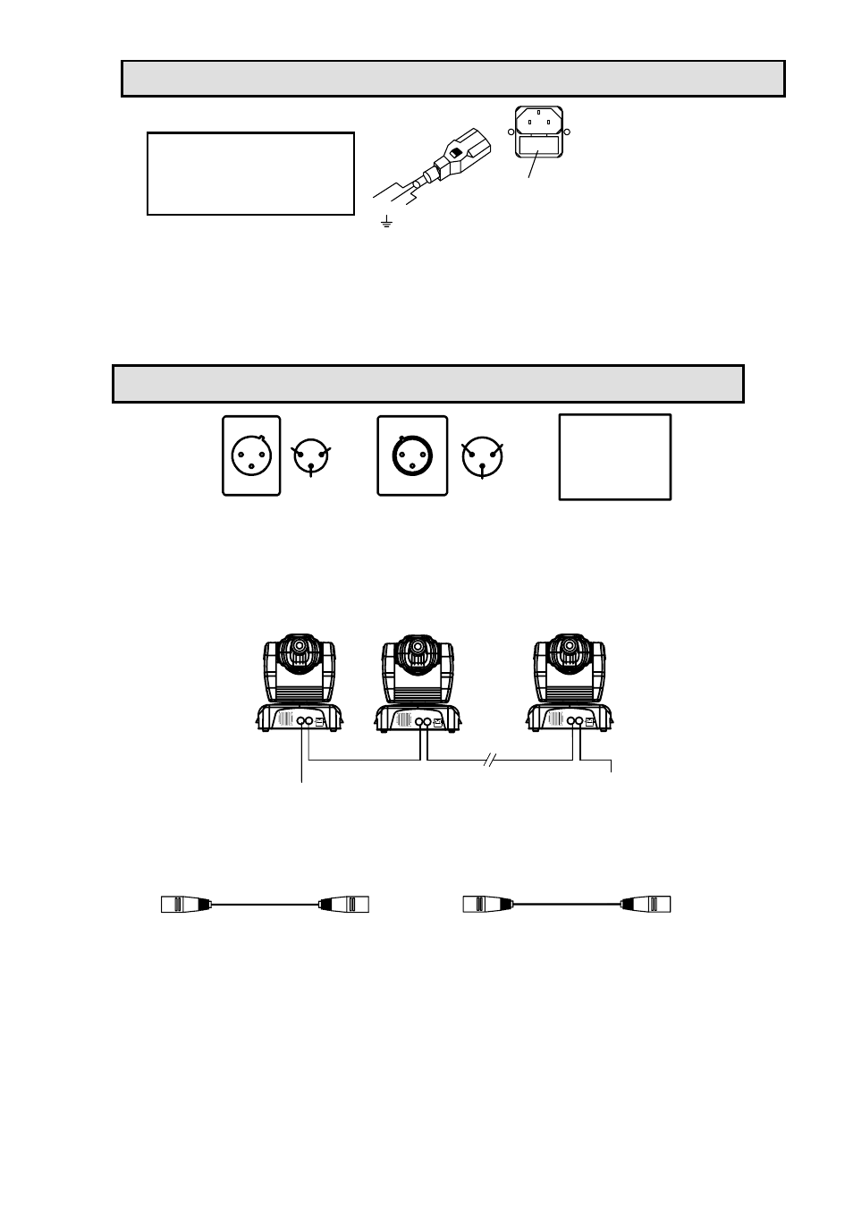
POWER SUPPLY – MAINS
FUSE F6.3A/250V
FUSE HOLDER
L E
N
L = BROWN
E = GREEN/YELLOW
N = BLUE
Use the plug provided to connect the mains power to the projector paying attention to the voltage and frequency
marked on the panel of the projector. It is recommended that each projector is supplied separately so that they
may be individually switched on and off.
IMPORTANT
It is essential that each projector is correctly earthed and that electrical installation conforms to all relevant
standards. Power consumption of the PILOT 150 is 280W.
CONTROL CONNECTIONS
DMX IN
1
2
3
1
2
3
DMX OUT
DMX 512
PIN
FUNCTION
1
2
3
GND
DATA -
DATA +
Connection between controller and projector and between one projector and another must be made with 2 core
screened cable, with each core having at least a 0.5mm diameter. Connection to and from the projector is via
cannon 3 pin XLR plugs and sockets which are included with the projector. The XLR's are connected as shown
in the table above. Note, care should be taken to ensure that none of the connections touch the body of the plug
or each other. The body of the plug is not connected in any way. The PILOT 150 accepts digital control signals
in standard DMX512 (1990) format.
DMX IN FROM
CONTROLLER
TERMINATOR
DMX IN
DMX IN
DMX IN
DMX OUT
DMX OUT
DMX OUT
No. 1
No. 2
No. n
Connect the controller’s output to the first fixture’s input, and connect the first fixture’s output to the second
fixture’s input. The rest may be deduced by analogy. Eventually connect the last fixture’s output to a DMX
terminator as shown in the figure above.
PILOT 150 uses 3-pin XLR plug / socket. If your controller uses 5-pin XLR plug / socket, you should use a
conversion cable from 5-pin to 3-pin as shown bellow.
5 PIN PLUG
Pin 1: GND (Screen)
Pin 2: Signal (data -)
Pin 3: Signal (data +)
Pin 4: N/C
Pin 5: N/C
3 PIN SOCKET
Pin 1: GND (Screen)
Pin 2: Signal (data -)
Pin 3: Signal (data +)
5 PIN SOCKET
Pin 1: GND (Screen)
Pin 2: Signal (data -)
Pin 3: Signal (data +)
Pin 4: N/C
Pin 5: N/C
3 PIN PLUG
Pin 1: GND (Screen)
Pin 2: Signal (data -)
Pin 3: Signal (data +)
When a DMX 512 signal is received the LED located near the digital display will illuminate green. When not
receiving a DMX signal the green and red LEDs will be off, and if the green LED flashes, it means that the DMX
signal is not correct.
5/14 pilot 150 manual.doc