Appendix 1, Irage pr-2014h – OmniSistem PR Mirage User Manual
Page 6
6/8
Appendix 1
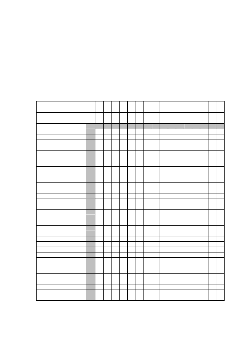
Table for setting address of DIP switch (for the controller mode)
The following table lists the setting codes of the address of the DIP switches, and the
luminaires are from No1 to No171. Each DIP switch has 10 switches with the number of #1,
#2, #3, #4, #5, #6, #7, #8, #9 and #10. (For the M
irage PR-2014H
, set all #10 switches
on the “OFF”.)
In the table, “0” means the switch is on the “OFF”, and “1” on the “ON”.
For example, if you want to look up the address setting of the No 50 luminaire, you will find
the NO 50 luminaire row (#1, #2, #3, #4, #5) with the codes of “0”, “0”, “1”, “0” , “1” and
column (#6, #7, #8, #9) with the codes of “0”, “0”, “1” , “0”. So set the #3, #5 and #8 switches
on the “ON”, and set the #1, #2, #4, #6, #7, #9 and #10 switches on the “OFF”.
#9 0
0
0
0
0
0
0
0
1
1
1
1
1
1
1
1
Setting Table of
Address Switches
#8 0
0
0
0
1
1
1
1
0
0
0
0
1
1
1
1
0=OFF
#7 0
0
1
1
0
0
1
1
0
0
1
1
0
0
1
1
1=ON
#6 0
1
0
1
0
1
0
1
0
1
0
1
0
1
0
1
#1 #2 #3 #4 #5
0
0
0
0
0
22
54
86
118
150
1
0
0
0
0
1
33
65
97
129
161
0
1
0
0
0
12
44
76
108
140
1
1
0
0
0
23
55
87
119
151
0
0
1
0
0
2
34
66
98
130
162
1
0
1
0
0
13
45
77
109
141
0
1
1
0
0
24
56
88
120
152
1
1
1
0
0
3
35
67
99
131
163
0
0
0
1
0
14
46
78
110
142
1
0
0
1
0
25
57
89
121
153
0
1
0
1
0
4
36
68
100
132
164
1
1
0
1
0
15
47
79
111
143
0
0
1
1
0
26
58
90
122
154
1
0
1
1
0
5
37
69
101
133
165
0
1
1
1
0
16
48
80
112
144
1
1
1
1
0
27
59
91
123
155
0
0
0
0
1
6
38
70
102
134
166
1
0
0
0
1
17
49
81
113
145
0
1
0
0
1
28
60
92
124
156
1
1
0
0
1
7
39
71
103
135
167
0
0
1
0
1
18
50
82
114
146
1
0
1
0
1
29
61
93
125
157
0
1
1
0
1
8
40
72
104
136
168
1
1
1
0
1
19
51
83
115
147
0
0
0
1
1
30
62
94
126
158
1
0
0
1
1
9
41
73
105
137
169
0
1
0
1
1
20
52
84
116
148
1
1
0
1
1
31
63
95
127
159
0
0
1
1
1
10
42
74
106
138
170
1
0
1
1
1
21
53
85
117
149
0
1
1
1
1
32
64
96
128
160
1
1
1
1
1
11
43
75
107
139
171