O.S. Engines FT-300 Gemini User Manual
Page 17
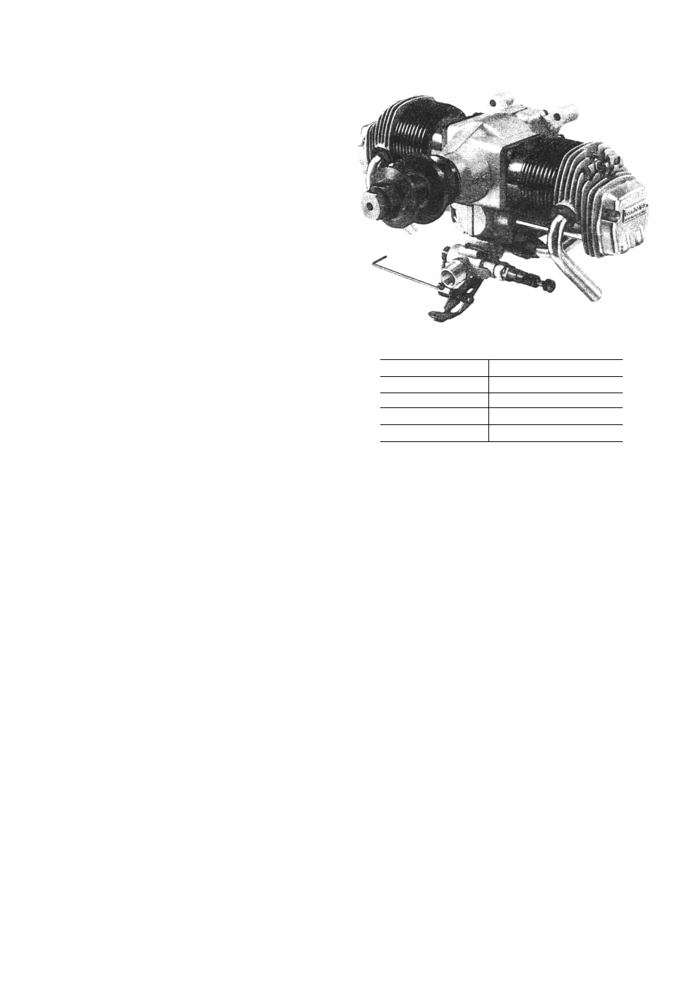
INSTRUCTIONS FOB O.S. FT-160 (GEMINI-160)
TWIN-CYLINDER FOUR STROKE ENGINE
IMPORTANT: Before attempting to operate your engine,
please read through this instruction sheet, as well as the
GEMINI SERIES Owner's Instruction Manual supplied, so
as to familiarize yourself with the controls and other fea-
tures of the engine. Also, pay careful attention to the
recommendations contained in the "Safety Instructions and
Warnings" leaflet also enclosed.
The O.S. FT-160 (Gemini-160) is a horizontally-opposed
twin-cylinder overhead-valve four-stroke-cycle engine of
26.5cc (1.62cu.in) displacement. It has the same external
dimensions and appearance as the FT-120-11 (Gemini-11)
but, whereas the Gemini-11 is restricted to 19.9cc (1.21
cu.in) to bring it within the 20cc displacement limit for
FAI Class F4C R/C Scale events, the Gemini-160 takes
advantage of slightly bigger cylinders, providing more
power for non-restricted events, or for sport flying.
Like the Gemini-ll, the Gemini-160 is a very refined engine.
The horizontally-opposed layout, typical of modern light
aircraft engine design, provides very smooth running
qualities and docile, trouble-free handling characteristics.
Production of the Gemini-160 and the Gemini-ll — a s with
their big brothers, the 40cc Super-Gemini and the 49cc
Super-Gemini-300 — was preceded by an exhaustive pro-
gramme of research and prototype testing. These engines
are, needless to say, built to the outstandingly high engi-
neering standards for which O.S. engines are famous word-
wide.
SPECIFICATIONS
Displacement
Bore
Stroke
Practical R.P.M.
Weight
13.26c.c.X2(0.809cu.in.X2)
27.7mm (1.091 in.)
22.0mm (0.866in.)
2.000-10.000
1,100gr. (38.8oz.)
TOOLS AND ACCESSORIES
The following tools and accessories are supplied with your
Gemini 160.
.
1. Radial Motor Mount Set:
Radial Motor Mount . . . . . . . . . . . . . . . . . . 1
Mount Fixing Screws (M5 x 25) . . . . . . . . . . . . 4
Lock Washers (05) . . . . . . . . . . . . . . . . . . . . 4
Blind Nuts (M5) . . . . . . . . . . . . . . . . . . . . . . 4
Engine Fixing Screws (M4
x 22). . . . . . . . . . . . 4
2. Set of leads for wiring glowplugs
Leads for glowplug with clip . . . . . . . . . . . . . . 2
Lead for earth (ground) . . . . . . . . . . . . . . . . . 1
3. Valve Adjusting Tool Kit
0.04mm. . . . . . . . . . . . . . . . . . . . . . . . . . . . . . . 1
0.10 mm . . . . . . . . . . . . . . . . . . . . . . . . . . . 1
Hexagonal (Alien) key (1.5 mm) . . . . . . . . . . 1
Wrench (5 mm) . . . . . . . . . . . . . . . . . . . . . . . 1
4. Needle-valve extension cable . . . . . . . . . . . . . . . 1
5. Knob for needle-valve extension (with set-screw) . . 1
6. Hook for needle-valve extension . . . . . . . . . . . . . 1
7. Choke valve rod . . . . . . . . . . . . . . . . . . . . . . 1
8. Woodruff key (spare) . . . . . . . . . . . . . . . . . . . 1
9. Scale Propeller Washer Set
Propeller washer . . . . . . . . . . . . . . . . . . . . 1
Propeller nut . . . . . . . . . . . . . . . . . . . . . . . 1
Screws to prevent propeller slippage (M3 x 32) . . . 4
10. Hexagonal (Alien) key (2.0 mm) . . . . . . . . . . . . 1
11. Hexagonal (Alien) key (2.5mm) . . . . . . . . . . . . 1
12. Hexagonal (Allen) key (3.0mm) . . . . . . . . . . . . 1
13. Wrench (5-6 mm) . . . . . . . . . . . . . . . . . . . . . 1
14. Wrench (7-8 mm) . . . . . . . . . . . . . . . . . . . . . 1
15. Wrench (10-12 mm) . . . . . . . . . . . . . . . . . . . . 1
16. Wrench (14-17 mm) . . . . . . . . . . . . . . . . . . . . 1
FUEL TANK
The suggested fuel tank size is 400 cc or 14 oz. This will
give approximately 10 minutes running time at full power,
or about 13-15 minutes when some part-throttle operation
is included. Fuel consumption also depends, of course, on
the size of propeller used.
PROPELLER
The choice of propeller depends on the weight of the model
and on the type of flying envisaged. Determine the best size
and type after practical experiment. As starting points, sug-
gested propel lers are 15 X 8, 16 X 6-8, 18 X 6-8 and 20 X 6.
If the Safety Propeller Locknut Assembly is used, instal-
lation procedure is as follows.
1) Ream the propeller center hole to 12 mm (0.472").
Make sure that the propeller is properly balanced.
2) Fit the propeller sleeve-nut and washer to propeller,
screw onto shaft and tighten firmly with 17 mm wrench
supplied.
Please refer to 'PROPELLER' section of GEMINI
SERIES Owner's Instruction Manual. If the dimension
"T" is between 14.5 mm and 18 mm (or 0.571" and
0.709"), add locknut spacer supplied as shown in Fig. 4.
If the dimension "T" is between 18 mm and 22-5 mm
(or 0.709" and 0.886"), it is not necessary to add the
spacer.
3) Finally, insert the Safety Propeller Locknut. Tighten
Locknut firmly (but not with excessive force) using
14 mm wrench.
CARBURETTOR ADJUSTMENT
The carburettor of your Gemini 160 has been factory set
for the approximate best result, but the setting may. in
some cases, vary slightly in accordance with fuel and cli-
matic conditions.
Remember, also, that, while the engine is being run-in and
the needle-valve is set on the rich side, the carburettor can-
not be expected to show its best response. Therefore, it is
recommended that you first run the engine with the throttle
settings as received. If, however, the desired throttle res-
ponse is not obtained after the completion of the running-
in period, the carburettor should be re-adjusted as follows.
Note: Idling speed adjustments should be carried out with the fuel
tank not more than half-full and with the battery disconnected
from the glowplugs.