7 electrical installation – NORAC 5467BC-4B-JD10 User Manual
Page 19
16
7 Electrical Installation
1. Locate the valve module installed on the NORAC valve block. Remove the plugs installed
in positions 7 and 8.
2. Connect the 2 pin connector on cables C10 into positions 7 and 8 on the valve module.
Connect the other end of cables C10 to the 2 pin connectors on the NORAC expansion
block (V02).
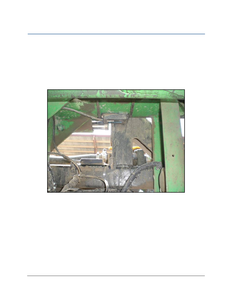
3. Disconnect and remove the two NORAC roll sensors (small rectangular box with a cable
running from it). See Figure 14 for locations.
Figure 14: Roll Sensor Locations
4. Connect the active roll sensor (E05) to the 8-way coupler (E11) where one of the roll
sensors was connected using cable C03 and a 2-way coupler (E12). Plug the unused
connector where the second roll sensor was connected using the 6-pin plug.
- UC4.5-BC-AP3 (35 pages)
- UC4.5-BC-AS1 (22 pages)
- UC4.5-BC-CS1 (34 pages)
- UC4.5-BC-CS2 (35 pages)
- UC4.5-BC-CS3 (36 pages)
- UC4.5-BC-CS5 (42 pages)
- UC4.5-BC-EU1 (42 pages)
- UC4.5-BC-FC1 (29 pages)
- UC4.5-BC-FC2 (32 pages)
- UC4.5-BC-FT1 (32 pages)
- UC4.5-BC-FT3 (33 pages)
- UC4.5-BC-GN1 (38 pages)
- UC4.5-BC-GN2 Part 1 (20 pages)
- UC4.5-BC-GN2 Part 2 (11 pages)
- UC4.5-BC-GN6 (22 pages)
- UC4.5-BC-HD1 (32 pages)
- UC4.5-BC-HD3 Part 1 (36 pages)
- UC4.5-BC-HD3 Part 2 (7 pages)
- UC4.5-BC-HD4 Part 1 (45 pages)
- UC4.5-BC-HD4 Part 2 (7 pages)
- UC4.5-BC-HD5 Part 1 (31 pages)
- UC4.5-BC-HD5 Part 2 (10 pages)
- UC4.5-BC-HD7 (39 pages)
- UC4.5-BC-HD9 (24 pages)
- UC4.5-BC-JD6 (37 pages)
- UC4.5-BC-JD7 (42 pages)
- UC4.5-BC-JD8 (35 pages)
- UC4.5-BC-JD8A (46 pages)
- UC4.5-BC-JD11 (33 pages)
- UC4.5-BC-MC1 (31 pages)
- UC4.5-BC-MC2 (31 pages)
- UC4.5-BC-MS1 (32 pages)
- UC4.5-BC-NT3 (31 pages)
- UC4.5-BC-NT4 (35 pages)
- UC4.5-BC-PS1 (38 pages)
- UC4.5-BC-RA1 (42 pages)
- UC4.5-BC-RA2 (27 pages)
- UC4.5-BC-RG2 (38 pages)
- UC4.5-BC-RG4 (36 pages)
- UC4.5-BC-RG5 (35 pages)
- UC4.5-BC-SC2 (33 pages)
- UC4.5-BC-SC4 (28 pages)
- UC4.5-BC-SM2 (30 pages)
- UC4.5-BC-SS1 (34 pages)
- UC4.5-BC-TA1 (36 pages)