NORAC UC4+BC+TA1 User Manual
Page 28
25
R2G) to the existing valve cable connectors
(LEFT DOWN, LEFT UP, RIGHT UP, and
RIGHT DOWN). Each function is labeled on
the wire.
12. Insert the 2-pin Deutsch plugs (P01) into
the existing valve connections that were
disconnected in the previous step.
13. Insert the 2-pin Deutsch tee (P2-R2) on
C13 into the bypass valve connection.
14. Connect the 6-pin Tower on the valve cable
(C03) to the mating 6-pin Shroud (S6A) on
C11.
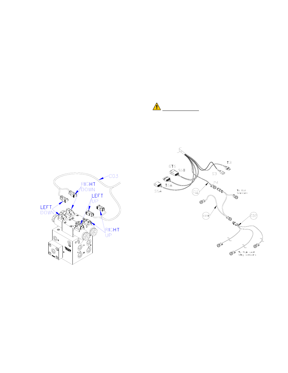
14. The connectors on the valve cable (C03)
are marked RIGHT UP, LEFT UP,
RIGHT DOWN and LEFT DOWN.
Cables labeled with UP go on the same side
as the hydraulic hoses.
Figure 29: Valve Cable Connections
15. Connect the CAN Node cable (C02B) to
the 4-pin AMP plug on C11 (Figure 30).
16. Route the CAN Node cable (C02B) to the
roll sensors. Follow existing cables and/or
hydraulic lines.
17. Connect 4-pin AMP connectors on C02B to
the roll sensors.
18. Connect the sensor branch cable (C02) to
the 4-pin AMP plug on C02B.
19. Route the sensor branch cable (C02) to the
wing and main sensors and connect to the
sensors. Follow existing cables and/or
hydraulic lines along the boom.
20. Cable-tie the installed cables every 12
inches.
IMPORTANT:
Provide enough slack in all cables to
account for the movement of the main
section, parallel lift, and FOLDING boom
movement.
Figure 30: Cable Configurations: C11,
C02and C02B