NORAC UC4+BC+JD8 Update User Manual
Page 6
4.
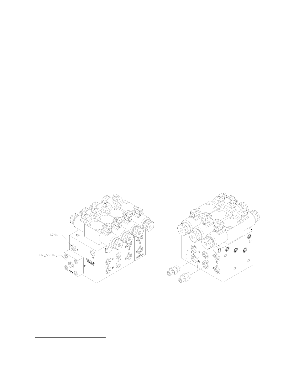
Remove the 6MB-4MOR fittings from the 1
st
and 2
nd
station of the NORAC valve block.
The 1
st
and 2
nd
stations are the two valve stations nearest the side with the pressure and
tank lines.
5.
Install the 6MB-6MOR (F05) fittings into the “A” and “B” ports of the 1
st
and 2
nd
stations on
the NORAC valve block. Tighten to 18 ft-lbs (24 Nm).
6.
Disconnect the existing hoses from the tilt cylinders. Remove the existing 90 degree fitting
on the rod end of each cylinder. Install a 6FORXR-6MORT fitting (F03) onto the ports of
each tilt cylinder. Reconnect the cylinder hoses and 90 degree fittings to the newly installed
tees.
7.
Connect one end of hoses H04 to the F03 fittings on the RIGHT tilt cylinder (Figure 3).
Route the hoses as shown in Figure 3. Connect the other end of hoses H04 to the
NORAC valve block “A” and “B” ports.
8.
Connect one end of hoses H02 to the F03 fittings on the LEFT tilt cylinder (Figure 3).
Route the hoses as shown in Figure 3. Connect the other end of hoses H02 to the
NORAC valve block “A” and “B” ports.
9.
The “raise” lines must be connected to the "B" ports of the NORAC valve block.
10.
The “lower” lines must be connected to the "A" ports of the NORAC valve block.
Figure 2: NORAC Valve Block Details
1
1
The valve block port orientation and filter cap may be different on all valve blocks. Some valve blocks may have
more or less stations than what is shown.