NORAC UC4.5-BC-RG4 User Manual
Page 24
21
13. Connect the valve interface cable (C03) to connector S6 on the valve extension cable
(C11).
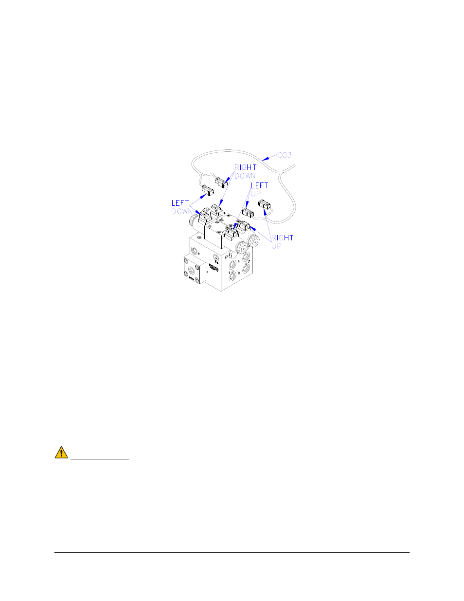
14. Connect the 2-pin connectors on the valve interface cable to the NORAC valve block, as
shown in Figure 21.
15. The connectors on the valve cable (C03) are marked RIGHT UP, LEFT UP, RIGHT
DOWN and LEFT DOWN. Cables labeled with UP go on the same side as the
hydraulic hoses.
Figure 21: Valve Cable Connections
16. Fasten the 8-way coupler to the boom with cable ties. Connect P6 on C11 to the 8-way
coupler using cable C08 and a 2-way coupler (E12).
17. Connect both roll sensors to the 8-way coupler.
18. Connect two cables (C05) to the 8-way coupler and route along the booms to the wing
sensors. Follow existing cables and hoses to be sure the cable will not be pinched or
stretched.
19. At the sensor brackets, attach a 2-way coupler with terminator (E20) to the sprayer boom.
The 2-way coupler with terminator is the white two way coupler. Plug the sensor and the
CANbus cable into the 2-way coupler.
IMPORTANT:
Provide enough slack in all cables to account for the movement of the main
section, parallel lift, and FOLDING boom movement.