NORAC UC4.5-BC-RG4 User Manual
Page 23
20
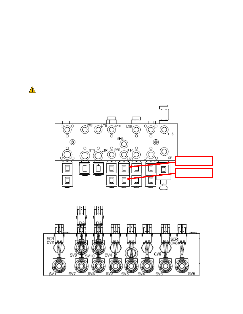
10. Unplug the existing connectors on the Rogator left and right boom control valve
connections. There are four connectors to unplug: SV9 (RIGHT UP), SV7 (RIGHT
DOWN), SV10 (LEFT UP) and SV8 (LEFT DOWN). Refer to Figure 20.
11. Connect four 2-pin Metri-Pack connectors of C12 (R2D, R2E, R2F and R2G) to the
matching connectors of Rogator cable(s), which are unplugged in Step 10. For each
connector, the function (e.g. “LEFT UP”) is labeled on the branch wire of C12.
12. If there is a bypass/jam valve (SV6), insert the tee (P2-R2) on C13 between the bypass/jam
valve connection on SV6 (Figure 20). Connect S3 on C13 to T3 on C11.
Alternate cabling is available from NORAC if the connectors on C12 (and
C13) do not match the valve block. Refer to Table 1 on page 8.
Figure
19:
Rogator Valve Block
Figure
20:
Solenoid Connections for Rogator Valve Block
MAIN DOWN
MAIN UP
- UC4.5-BC-AP3 (35 pages)
- UC4.5-BC-AS1 (22 pages)
- UC4.5-BC-CS1 (34 pages)
- UC4.5-BC-CS2 (35 pages)
- UC4.5-BC-CS3 (36 pages)
- UC4.5-BC-CS5 (42 pages)
- UC4.5-BC-EU1 (42 pages)
- UC4.5-BC-FC1 (29 pages)
- UC4.5-BC-FC2 (32 pages)
- UC4.5-BC-FT1 (32 pages)
- UC4.5-BC-FT3 (33 pages)
- UC4.5-BC-GN1 (38 pages)
- UC4.5-BC-GN2 Part 1 (20 pages)
- UC4.5-BC-GN2 Part 2 (11 pages)
- UC4.5-BC-GN6 (22 pages)
- UC4.5-BC-HD1 (32 pages)
- UC4.5-BC-HD3 Part 1 (36 pages)
- UC4.5-BC-HD3 Part 2 (7 pages)
- UC4.5-BC-HD4 Part 1 (45 pages)
- UC4.5-BC-HD4 Part 2 (7 pages)
- UC4.5-BC-HD5 Part 1 (31 pages)
- UC4.5-BC-HD5 Part 2 (10 pages)
- UC4.5-BC-HD7 (39 pages)
- UC4.5-BC-HD9 (24 pages)
- UC4.5-BC-JD6 (37 pages)
- UC4.5-BC-JD7 (42 pages)
- UC4.5-BC-JD8 (35 pages)
- UC4.5-BC-JD8A (46 pages)
- UC4.5-BC-JD11 (33 pages)
- UC4.5-BC-MC1 (31 pages)
- UC4.5-BC-MC2 (31 pages)
- UC4.5-BC-MS1 (32 pages)
- UC4.5-BC-NT3 (31 pages)
- UC4.5-BC-NT4 (35 pages)
- UC4.5-BC-PS1 (38 pages)
- UC4.5-BC-RA1 (42 pages)
- UC4.5-BC-RA2 (27 pages)
- UC4.5-BC-RG2 (38 pages)
- UC4.5-BC-RG5 (35 pages)
- UC4.5-BC-SC2 (33 pages)
- UC4.5-BC-SC4 (28 pages)
- UC4.5-BC-SM2 (30 pages)
- UC4.5-BC-SS1 (34 pages)
- UC4.5-BC-TA1 (36 pages)