8 hydraulic installation, 1 valve assembly, 8hydraulic installation – NORAC UC4.5-BC-NT4 User Manual
Page 25
22
8
Hydraulic Installation
Ensure all pressure has been bled from the system before disconnecting any lines
or fittings. Hydraulic pressure will exist on the wing tilt circuits unless the wings
are being supported by other means. The hydraulic installation may be performed
with the wings in transport position, resting on the ground or with the tilt cylinders
fully extended.
Component failure due to oil contamination is not covered under the NORAC
UC4.5 system warranty. It is recommended that a qualified technician perform the
hydraulic installation.
8.1
Valve Assembly
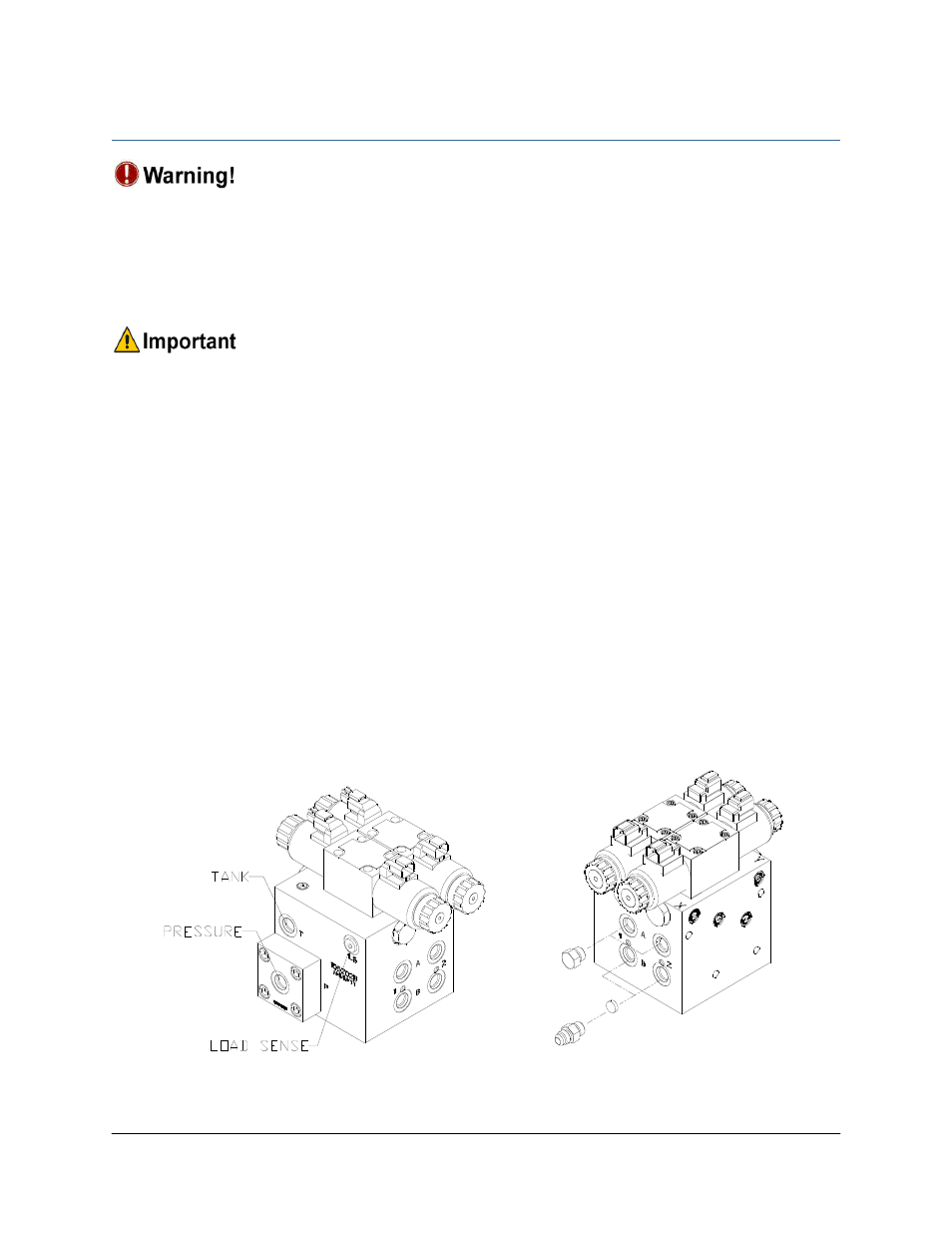
1. On a clean surface remove the plastic plugs from the block.
2. Install two 6MB-6MOR (F02) fittings on the “P” and “T” ports on the NORAC block.
Tighten to 18 ft-lbs (24 Nm).
3. Insert the orifices (F08) into the “B” ports.
4. Install the 6MB-6MOR (F02) fittings into the “B” ports on the NORAC block. Tighten to
18 ft-lbs (24 Nm).
5. Install the 6MBP plugs (F01) into the “A” ports of the NORAC valve block and tighten to 18
ft-lbs.
Figure 25: NORAC Valve Block Details