NORAC UC4.5-BC-NT4 User Manual
Page 23
20
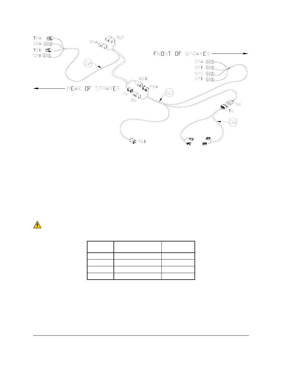
Figure 23: Valve Cable Configurations Outside of Cab
5. Route connector R6B/P6 on cable C14 to the front of the sprayer just behind the sprayer
boom disconnect point.
6. Connect cable C15 and C14 together and route the ends of C15 so they are near the
sprayer boom valve block at the front of the sprayer.
7. Disconnect the four metri-pack connectors for the boom tilt cylinders from the Nitro valve
block and connect them to their respective connectors on cable C15. Use Table 1 to
match the connectors together.
Each metri-pack connector on C15 is marked with its function.
Table 1: Boom Tilt Functions
Sprayer
Connector
Function
NORAC
Connection
BM17
Left Boom UP
S2A
BM16
Left Boom DOWN
S2B
BM 15
Right Boom UP
S2C
BM14
Right Boom DOWN
S2D
8. Connect connector T6 on cable C03 to S6 on C15. Connect the 2-pin connectors on C03
to the NORAC valve block, as shown in Figure 24.
9. The connectors on the valve cable (C03) are marked RIGHT UP, LEFT UP, RIGHT
DOWN and LEFT DOWN. Cables labeled with UP go on the same side as the
hydraulic hoses.