NORAC UC4.5-BC-JD7 User Manual
Page 21
19
19
8. Connect the 6-pin shroud on C04 to 6-pin tower on the junction cable (C12).
9. Connect the 6-pin tower on the valve cable (C03) to 6-pin shroud on C12.
10. C12 has a screw terminal. It must be connected to the frame of the sprayer. Scrape any
paint off the frame where the terminal is mounted. A good location is the bolt holding the
JD wiring harness next to the large connector at the rear of the sprayer frame.
The terminal must be attached directly to the sprayer frame NOT the parallel
linkage. An improper ground can cause UC4.5 Spray Height Control system
malfunctions.
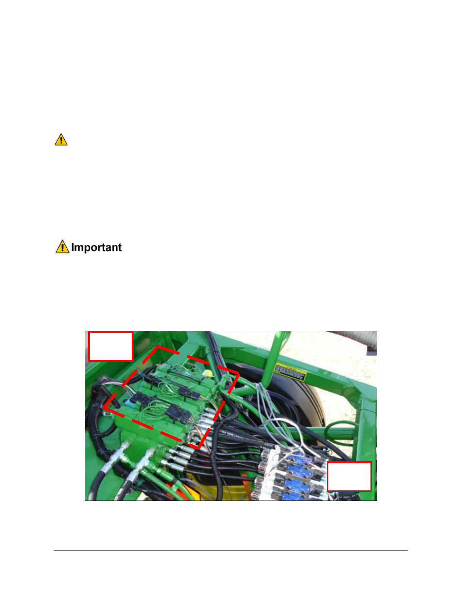
11. Insert the connectors labeled Main Up and Main Down on C12 into the main lift
connectors on the John Deere solenoids (Figure 19).
12. Insert the other connectors on C12 into the tilt connectors on the John Deere solenoids
according to the labels on the wires.
There is one set of different connectors (M14 and M15) included with the interface
cable (C12). Some John Deere sprayers use this connector on the left down
function. If the sprayer has this connector, remove the existing NORAC
connectors using the included pin removal tool. Insert the wires into the new
connector and ensure they are in the same position as they were in the previous
connector.
Rear of
Sprayer
Front of
Sprayer