7 electrical installation – NORAC UC4.5-BC-JD7 User Manual
Page 19
17
17
7 Electrical Installation
1. Install the UC4.5 Control Panel (E01) in the cab of the sprayer. Mount the panel where it
will be clearly visible and within easy reach of the operator.
A good spot to mount the UC4.5 control panel is on the right hand side of the cab to the
Roll Over Protection Bar. Four pilot holes for the screws provided need to be drilled to
facilitate the control panel mounting.
If desired, a mounting bracket (part #A53255) can be purchased from your local John Deere
dealer to allow the UC4.5 control panel to be mounted to the existing John Deere terminal
mount. Another option is to purchase an adapter for the flexible panel mount that has a
3/8" NC threaded stud on the end to bolt through the existing JD mount. These are
available at your local outdoor store as a RAM mount part number RAM-B-236. (See
http://www.ram-mount.com/
)
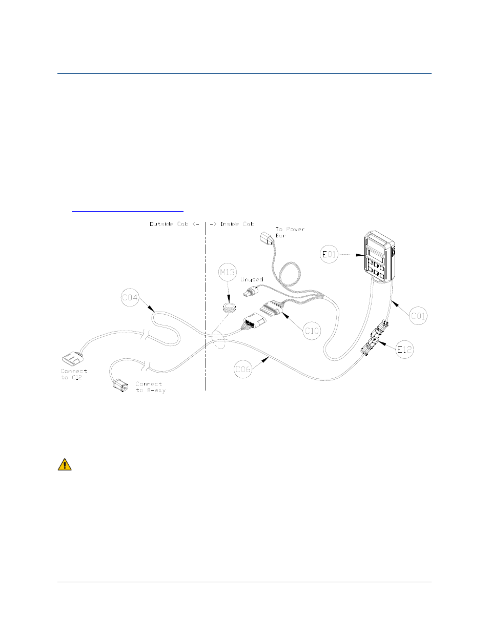
Figure 16: Cable Configurations: C01, C04, C06 and C10
2. Connect the UC4.5 power cable (C10) to the 16-pin connector on the back of the UC4.5
Control Panel in the cab. Connect C01 to the 4-pin connector on the back of the UC4.5
Control Panel. Cable tie C10 and C01 to the RAM mount to help provide strain relief.
Ensure the UC4.5 Control Panel’s power is OFF for the remaining installation.
(Bottom of switch pressed IN).
3. Connect C06 to C01 using the 2-way coupler (E12).
4. Plug the 3-pin connector on C10 to the power bar in the cab.
5. Route the free ends of C10 and C06 along the side of the cab post and under the floor mat.