MOOER ABY MK2 User Manual
Main features, Diagrams panel instruction specification, Precautions
Main Features
Channel Switch Pedal
A/B/Y Jack: 1/4” monaural jack
Power Requirements: AC adapter 9V DC (center minus plug), can
work without power (LED doesn’t work). Recommended to use Mooer
Micro Power
Current Draw: 8 mA
Dimensions: 93.5mm (D) × 42mm (W) × 52mm (H)
Weight: 145g
Accessories: Owner’s Manual
*
Disclaimer: Any specification’s update won't be amended in this manual.
The comprehensive channel switch pedal, can switch the one way
signal to two different outputs, applicable for the circuit of instrument,
amplifier, speaker (be sure to use speaker cable) and pedalboard
The design of mode-choosing switch, which enables A, B channels
transfer from respectively to simultaneously
In both modes, ABY can be used in both positive and negative directions,
the signal path can flow from A/B to Y, or from Y to A/B
Can work without power supply (LED will not light up)
Full metal shell
Very small and compact design
True bypass switch
DC 9V adapter power supply
A/B Mode: Y(instrument) →A/B(amplifier A / amplifier B), stepped
on the foot switch to select the amplifier
A / B
Y(A&B)
A:RED
B:BLUE
Y:PINK
A(instrument A)/B(instrument B) →Y(amplifier) Stepped
on the foot switch to select the instrument
A / B
Y(A&B)
A:RED
B:BLUE
Y:PINK
A&B Mode: In this mode, can connect any A, B, Y connector according
to personal demand
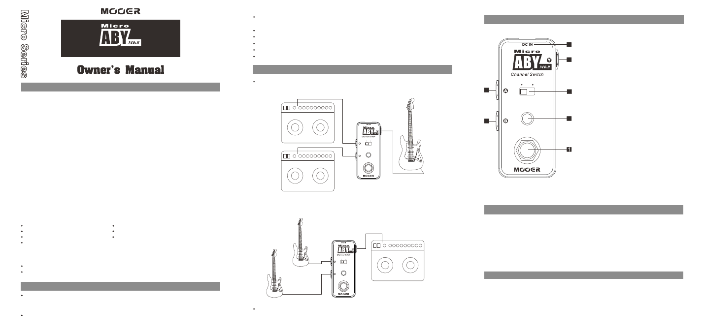
1. CHANNEL SELECT Footswitch:
Push down the footswitch to toggle
between channel A and channel B
(in A&B mode, footswitch is invalid).
3. LED Light:
4. DC IN Power Jack:
5. A Jack:
1/4” mono audio jack, connect instruments
or speakers and other devices.
In A/B mode, indicates in A channel
or B channel; the red lights mean in
A channel, the blue lights mean in B
channel; In A&B mode, LED lights
turn into pink.
A / B
Y(A&B)
A:RED
B:BLUE
Y:PINK
6
5
2
4
7
3
2. MODE SELECT Switch:
Select A/B mode or A&B mode.
For power supply, use a 9-volt
DC regulated AC adapter (plug
polarity is positive on the barrel
and negative in the center).
6. B Jack:
1/4” mono audio jack, connect instruments
or speakers and other devices.
7. Y Jack: 1/4” mono audio jack, connect instruments or speakers and other
devices.
Diagrams
Panel Instruction
Specification
PLEASE READ CAREFULLY BEFORE PROCEEDING
Power Supply
Connections
Always turn off the power of this and all other equipment before connecting or
disconnecting, this will help prevent malfunction and / or damage to other devices.
Also make sure to disconnect all connection cables and the power cord before
moving this unit.
Cleaning
Clean only with a soft, dry cloth. If necessary, slightly moisten the cloth.
Do not use abrasive cleanser, cleaning alcohol, paint thinners, wax, solvents,
cleaning fluids, or chemical-impregnated wiping cloths.
Interference with other electrical devices
Radios and televisions placed nearby may experience reception interference.
Operate this unit at a suitable distance from radios and televisions.
Location
To avoid deformation, discoloration, or other serious damage, do not expose
this unit to the following conditions:
Direct sunlight
Heat sources
Magnetic fields
Extreme temperature or humidity
Excessive dusty or dirty location
High humidity or moisture
Strong vibrations or shocks
Please connect the designated AC adapter to an AC outlet of the correct voltage.
Please be sure to use only an AC adapter which supplies 9V (±10%) DC, center
minus. The maximum working voltage shall not exceed 12V, otherwise may be
dangerous equipment damage, fire or other problems.
Unplug the AC power adapter when not using or during electrical storms.
Precautions
FCC certification
This device complies with Part 15 of the FCC Rules. Operation is subject
to the following two conditions:
This device may not cause harmful interference.
This device must accept any interference received, including interference
that may cause undesired operation.