Loader protocol layer – Maxim Integrated MAXQ20-Based Microcontroller Bootloader Command Reference User Manual
Page 3
MAXQ20-Based Microcontroller Bootloader Command Reference
3
Loader Protocol Layer
Bootloader commands are segregated by command family, designated. 0 to F. Commands within a family have a
common functionality. Family F commands are target-specific that have special features in common.
All bootloader commands begin with a single command byte. The high four bits of this command byte define the
command family (from 0 to 15), while the low four bits define the specific command within that family.
After each command has completed, the loader will output a ‘prompt’ byte to indicate that it has finished the
operation. The prompt byte is the single character ‘>’ (byte value 03Eh).
After each bootloader command the error code should be read by means of the Get Status command (04h). If the
status byte is a value other than 00h then an error has occurred and the host should take the appropriate action.
All commands in Family 0 may be executed whether or not the security lock is set or password protection
enabled. All other commands may only be executed if the security lock is cleared (SL=0).
When providing addresses for code or data read or write to bootloader commands, all addresses run from 0000h
to (memory size – 1).
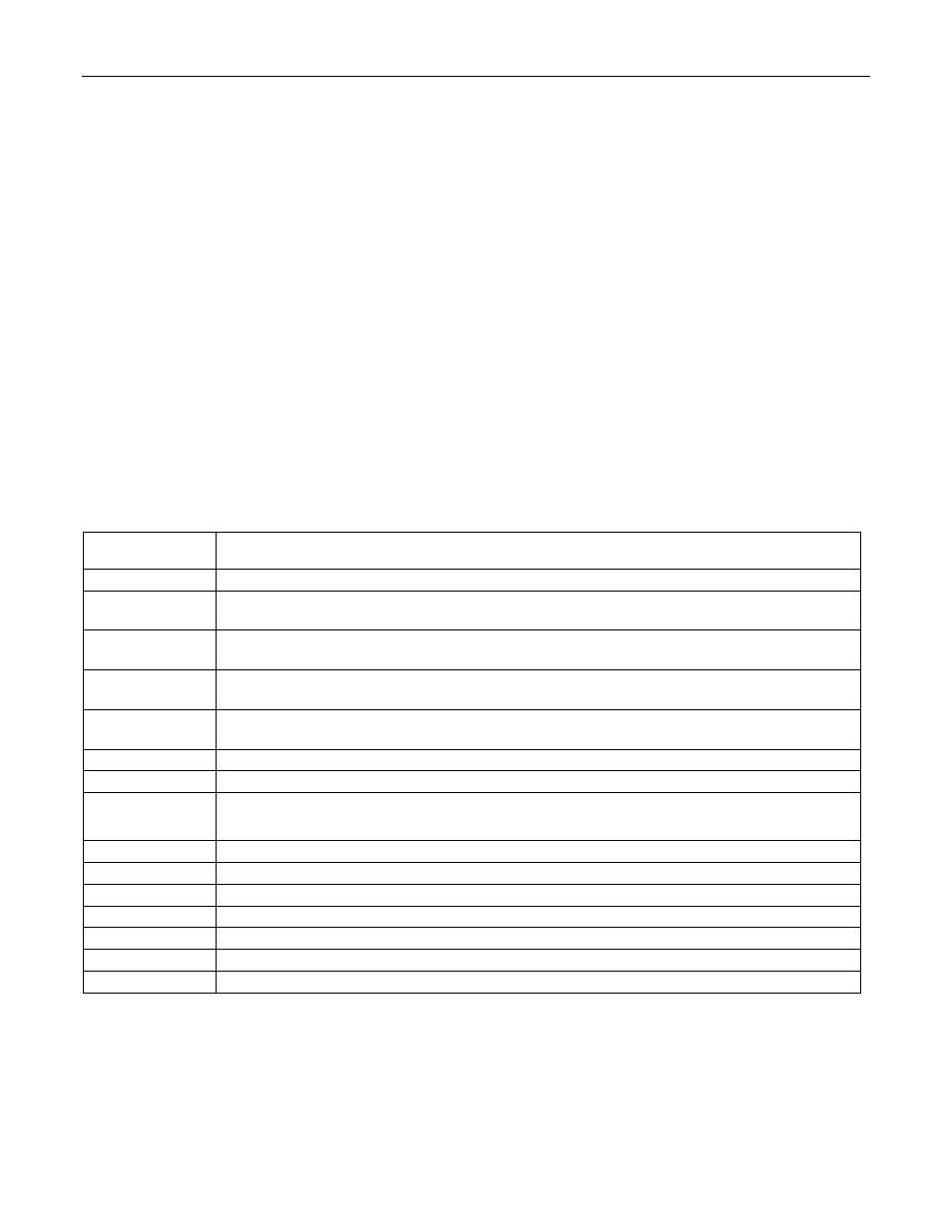
Table 1. Bootloader Status Codes
STATUS
VALUE
MEANING
00
No Error. The last command completed successfully.
01
Family Not Supported. An attempt was made to use a command from a family which the
bootloader does not support.
02
Invalid Command. An attempt was made to use a nonexistent command within a
supported command family.
03
No Password Match. This status code is returned when an attempt is made to use a
command other than a Family 0 command when the security lock is set (SL=1).
04
Bad Parameter. The parameter (address or otherwise) passed to the command was out of
range or otherwise invalid.
05
Verify Failed. The verification step failed on a Load/Verify or Verify command.
06
Unknown Register. An attempt was made to read from or write to a nonexistent register.
07
Word Mode Not Supported. An attempt was made to set word mode access, but the
bootloader supports byte mode access only.
08
Master Erase Failed. The bootloader was unable to perform master erase.
09
Page Erase Failed. An attempt to erase a flash page failed.
10
Not Implemented. The command or feature was not implemented.
11
Timeout. A hardware timeout occurred during the operation.
12
Invalid Mode.
13
Hardware Failure.
14
Loader Lock Failed. Writing the loader lockout pattern to flash failed.