Make Noise Analog Memory User Manual
Page 9
9
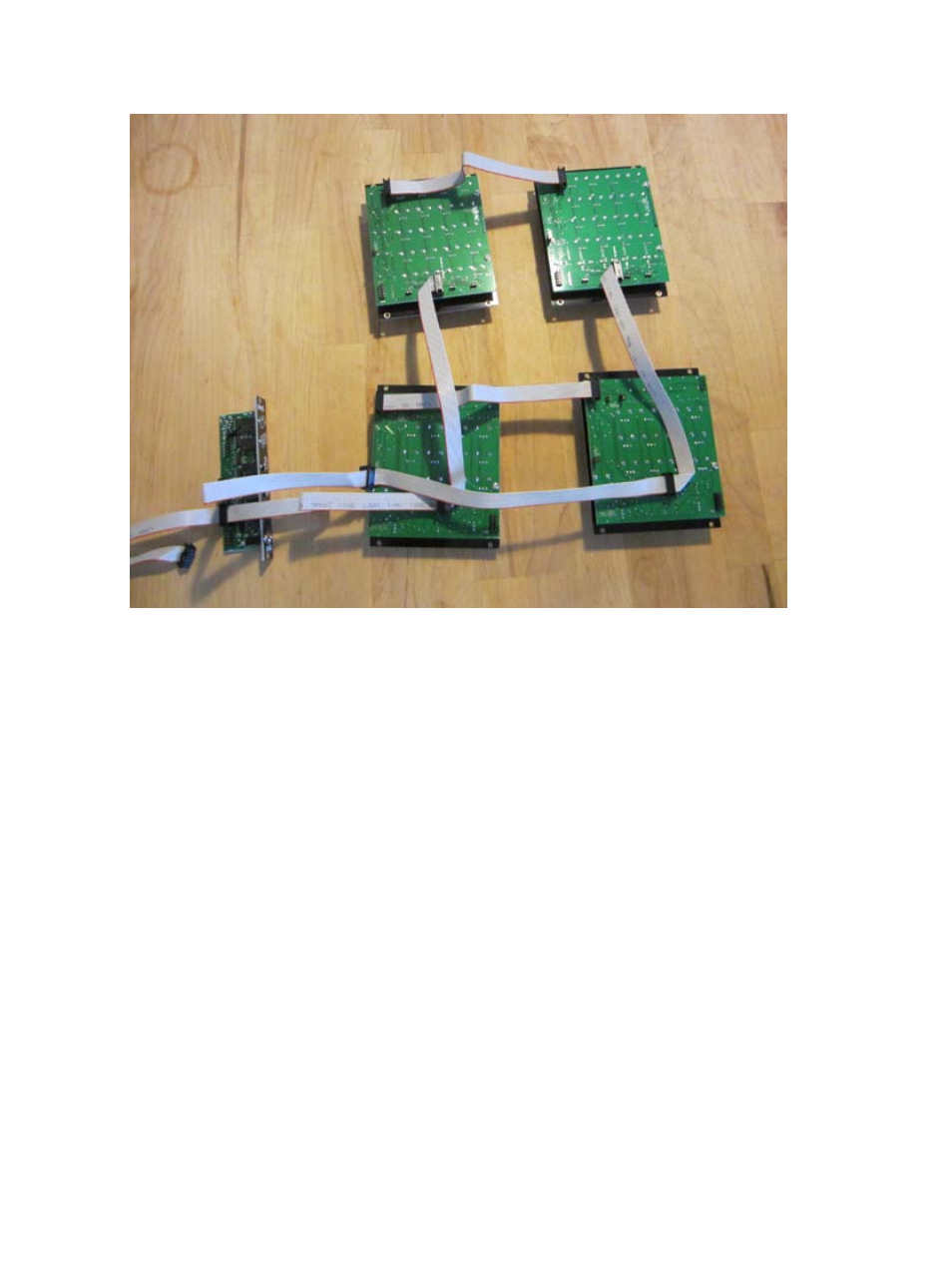
Connecting 2 Analog Memory to 2
Pressure Points
Connect one of the remaining 3 connectors to the 10 pin header on
the Pressure Points that is marked “EXPND.” You will need to re-
move all 4 of the small black “jumpers” that are covering the pins of
this header before you attach the EXPAND CABLE. Maintain proper
orientation of the cable, keeping the Red Stripe DOWN. Connect
each Analog Memory to the Pressure Points with which you wish to
control it.
Now connect the EXPAND Cables to the 10 pin headers on the
BRAINS marked “Points 1-4” and “Points 5-8.” The EXPAND Cable
coming of the Pressure Points nearest to the BRAINS is connected
to the “Points 1-4.”
Using the provided CHAIN cable, connect the two Analog Memory
modules at the 10 pin header marked “CHAIN.” Maintain proper ori-
entation of the cable, keeping the Red Stripe DOWN at both ends.
Analog Memory(s) that are not the that last in the CHAIN will need
to have the jumper marked “Close 4 Master” removed.
Please see the Pressure Points and BRAINS manuals for details on
proper jumper settings and connection for Pressure Points/ BRAINS,
and follow those instructions.
NOTE: Power Cables removed in photo for clarity.