Vermont castings, majestic products: dvr33, Vertical sidewall installation, Step 6 – Vermont Casting DVR33 User Manual
Page 16: Step 2, Step 1, Step 3, Step 4, Step 5
16
Vermont Castings, Majestic Products: DVR33
10004920
Vertical Sidewall Installation
#8 Screws (2)
#8 Screws (2)
12"
(304.8 mm)
max.
Firestop
(Side View)
CFM135a
Fig. 25 Adjustable zero clearance sleeve.
Zero clearance sleeve is required only
for combustible walls.
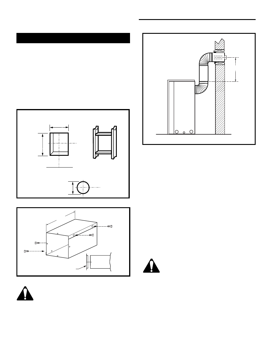
Fig. 26 Vertical height requirements.
Always install horizontal venting on
a level plane.
Step 6
Use the appropriate length of pipe sections—telescopic
or fixed—and install. The sections which go through
the wall are packaged with the starter kit, and can be
cut to suit if necessary.
NOTE: Sealing vent pipe and firestop gaps with
high temperature sealant will restrict cold
air being drawn in around fireplace.
X
Step 2
Measure wall thickness and cut zero clearance sleeve
parts to proper length (12” [305 mm] max.). Assemble
sleeve and attach to firestop with #8 sheetmetal
screws (supplied). Install firestop assembly (Fig. 25).
Step 1
Locate vent opening on the wall. It may be necessary
to first position the fireplace and measure to obtain
hole location. Depending on whether the wall is
combustible or noncombustible, cut opening to size.
(For combustible walls, frame in opening first (Fig. 24).
Combustible Walls: Cut a 9
³⁄₈
”H x 9
³⁄₈
” W (240 mm x
240 mm) hole through the exterior wall and frame.
Noncombustible Walls: Hole opening must be 7
¹⁄₂
”
(190 mm) in diameter.
Step 3
Place fireplace into position. Measure the vertical
height (X) required from the base of the flue collars to
the center of the wall opening (Fig. 26).
Step 4
Apply a bead of high temperature silicone sealant to
the inner and outer flue collars of the fireplace and
using appropriate length of pipe section(s) attach to
fireplace with three (3) screws. Follow with the installa-
tion of the inner and outer elbow, again secure joints
as described in the ‘Connecting Vent Pipe’ section.
Step 5
Measure the horizontal length requirement including a
2” (50 mm) overlap, i.e. from the elbow to the outside
wall face plus 2” (50 mm)—or the distance required if
installing a second 90˚ elbow (Fig. 27).
Vent Opening: Combustible Wall
Framing Detail
Fireplace Hearth
9
3
/
8
”
(240 mm)
7
1
/
2
” Dia.
(190 mm)
VO584-100
Vent Opening:
Noncombustible Wall
9
3
/
8
”
(240 mm)
Fig. 24 Locate vent opening on wall.
VSW height X