Lippert Components In Wall Slide-Out System User Manual
Page 6
Rev: 11.21.2014
Page 6
IN-WALL™ Slide-out Owner's Manual
Extend and Retract Switch Connections
Common connection on controller goes to common connection on extend and retract
switch. Extend and retract connections on the controller go to the extend and retract
terminals on the switch. Switch is powered by the OEM supplied 12V DC power source.
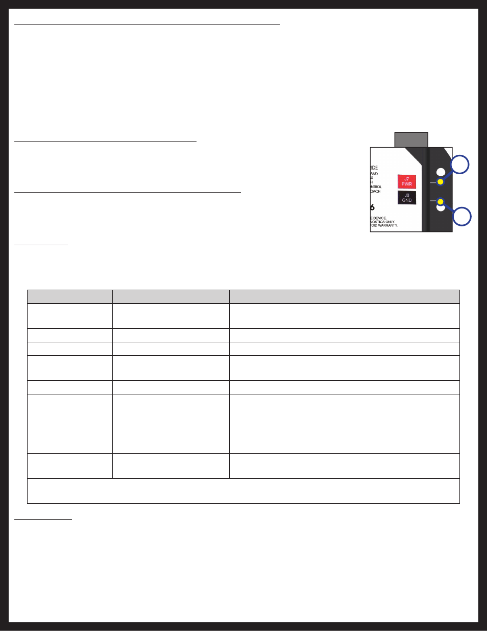
Power and Ground Connections at the Controller
Power and ground are supplied to the controller through the spade terminals located
on the right hand side of the controller (Fig. 8A, 8B). 12V DC is recommended. A 10ga
wire is the minimum size recommended.
Fig. 8
A
B
Error Code
Name
Description
2
Battery Drop Out
Battery capacity low enough to drop below 6 volts
while running.
3
Low Battery
Voltage below 8 volts at start of cycle.
4
High Battery
Voltage greater than 18 volts.
5
Excessive Motor Current
High amperage, also indicated by 1 side of slide
continually stalling.
6
Motor Short Circuit
Motor or wiring to motor has shorted out.
8
Wire Short Between
Controller and Motor
(Error named "Hall Sig
Not Present" on Rev. B
controller)
Encoder is not providing a signal, which is usually a
wiring problem.
9
Hall Power Short To
Ground
Power to encoder has been shorted to ground,
which is usually a wiring problem.
When an error code is present, the board needs to be reset. Energizing the extend/retract switch resets
the board. Energize the extend/retract switch again for normal operation.
Low Voltage
The Lippert IN-WALL™ Slide-out Controller is capable of operating the room with as little as 8 volts. But at these
lower voltages the amperage requirement is greater. Check voltage at the controller, see pages 4 and 5 for the
location of power connections. If voltage is lower than 11 volts, it is recommended that the battery be placed on
a charger until it is fully charged. It may be possible to "jump" the RV's battery temporarily to extend or retract the
room. Consult the RV manufacturer’s owners manual on the procedure for "jumping" or charging the battery.
NOTE: Never "jump" or charge the battery from the power connections on the IN-WALL™ Controller. Always
do this at the battery.
Electronic Manual Override (Controllers C-1 and C-2 Only)
NOTE: See (Fig. 5) for locations of the mode button and LEDs.
1. Press the mode button on the controller six times and hold on the seventh for five seconds to enter
electronic manual override mode.
2. Use the extend/retract switch to move both motors in or out.
NOTE: Over-current and short circuit detection are disabled. Electronic manual override provides 12V
directly to both motors.
3. To exit the mode, push and hold the mode button until the LEDs begin to blink simultaneously. Exiting
the override mode resets the motor positions.
Error Codes
During operation when an error occurs the board will use the LEDs to indicate where the problem exists.
For motor-specific faults the green LED will blink 1 time for motor 1, and 2 times for motor 2. The red LED will blink
from 2 to 9 times depending on the error code.