Lippert Components Ground Control 3.0 OEM User Manual
Page 3
Rev: 01.30.2015
Page 3
Ground Control 3.0 OEM Installation Manual
Preparation
1. Remove all loose items from the front storage compartments of the 5th wheel.
2. Analyze the unit. Determine where the rear jack brackets, controller, and touch pad will be mounted
on the unit. The rear jack brackets should be mounted approximately 1 foot behind the rear axle
hanger and be aligned with each other. The controller should be mounted in the center of the unit
in compliance with RVIA Gas Codes as the controller connections are not spark-proof. The touch pad
should be mounted in a compartment on the side of the unit so that the operator will have a view of
the hitch pin while using the touch pad. The touch pad MUST also be protected from the elements.
NoTE: The landing gear will be installed to the frame of the unit by LCI.
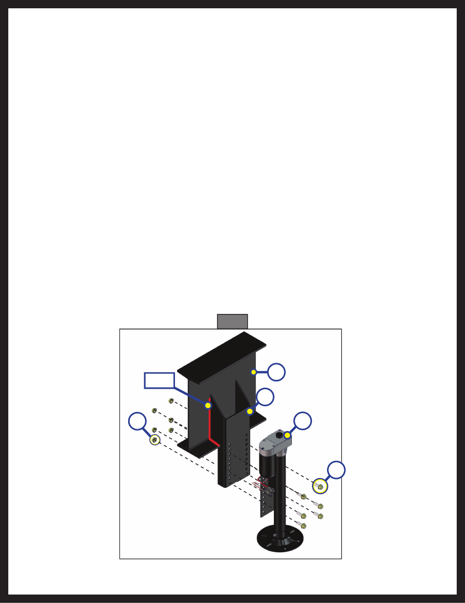
Installation - Rear Jacks
1. Determine position and ground clearance requirements for the rear jacks (Fig. 1D). The rear jack
brackets (Fig. 1C) should be mounted approximately 1 foot behind the rear axle hanger and be aligned
with each other.
NoTE: When fully retracted, rear jacks should be equal to the departure angle or a minimum of 7" of ground
clearance.
2. Mark jack mounting bracket (Fig. 1C) locations on the main frame rail.
3. Clamp the bracket to the main frame rail (Fig. 1B) in the marked position.
4. Weld the bracket to the main frame rail (Fig. 1B).
5. Bolt the rear jacks (Fig. 1D) to the mounting brackets (Fig. 1C) using six bolts (Fig. 1E) and nuts (Fig. 1A)
per jack. Tighten the bolts to 90 lb.-ft. of torque.
6. Connect the wire harnesses to the rear jack motor wires and run the harnesses to the compartment
where the controller will be mounted.
NoTE: LCI recommends zip-tying the harnesses tight against the rear jack motors to prevent damage to the
harnesses.
Fig. 1
E
C
A
D
Weld
B