Operational overview, Operational overview -4, 4 introduction – Compaq 1124 User Manual
Page 11: Figure 1-2. repeater front panel, Figure 1-3. repeater back panel
. . . . . . . . . . . . . . . . . . . . . . . . . . . . .
1-4
Introduction
Writer: Chris Seiter Project: Introduction Comments: 185810-001/707119-001
File Name:10024_1.DOC Last Saved On:3/13/96 5:15 PM
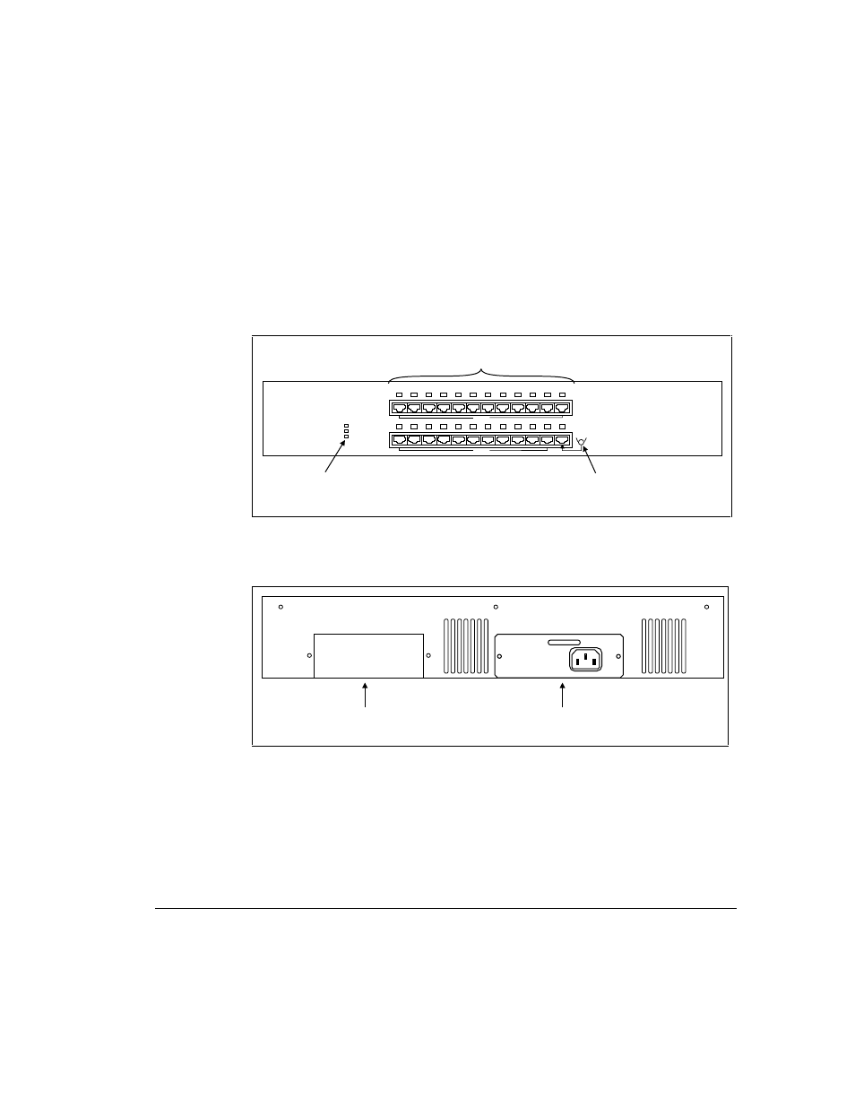
Operational Overview
This section provides an overview of the repeater's components, which include
the LED indicators, RJ-45 ports, and uplink ports, and discusses the basic
functionality of the repeater. Figures 1-2 and 1-3 show the repeater's front and
back panel.
MDI-X
MDI-X
1
13
2
14
3
15
4
16
5
17
6
18
7
19
8
20
9
21
10
22
11
23
12
24
COL
PWR A
PWR B
MDI
MDI-X
Power Supply and
100Base-T Collision
Status Indicators
Uplink Switch
(24) RJ-45 UTP Ports
(for 100Base-TX)
Figure 1-2. Repeater Front Panel
PWR B
PWR A
Optional Power Supply B
(Backup)
Power Supply A
(Pre-installed)
Figure 1-3. Repeater Back Panel
- Netelligent 8500 (3 pages)
- 127453-B21 (4 pages)
- AlphaPC 164LX (82 pages)
- QUICKSPECS 294162-B21 (1 page)
- PowerLeap JP2 (6 pages)
- 5900 (1 page)
- 517212-001 (26 pages)
- SmartCore Express SMA200 (42 pages)
- 212953-B21 (2 pages)
- NC3132 (4 pages)
- 705 (2 pages)
- au-Series (11 pages)
- AlphaPC 164SX (72 pages)
- 21264 (356 pages)
- PROLIANT 3000 (137 pages)
- ProLiant p-Class (24 pages)
- TL895 (10 pages)
- Microcom 420 (2 pages)
- uSign Signature Capture Module uSign 200 (18 pages)
- Universal Notebook Power Adapter SPS-2406 (4 pages)
- RAID ARRAY 3000 EK-SMCPO-UG. C01 (112 pages)
- DA-10121 (3 pages)
- AlphaStation XP1000 (16 pages)
- MICROSPACE MSEBX800 (53 pages)
- Contec RS-232C (77 pages)
- SDLT 220GB (8 pages)
- Cabinet H9A11 (32 pages)
- MTEK6000 (81 pages)
- SANetworks Network View DA10682 (6 pages)
- AA-RHGWB-TE (320 pages)
- OXYGEN VX1 (29 pages)
- COM Express Extension (24 pages)
- Lithium-ion battery (7 pages)
- 164SX (72 pages)
- 3200 (211 pages)
- AA-Q88CE-TE (320 pages)
- MSB900L (66 pages)
- WL100 (2 pages)
- Wireless LAN 100 (2 pages)
- 1000 LX (4 pages)
- AAR-88LB-TE (42 pages)
- PC100 (66 pages)
- VAX 7000 Model 810 (9 pages)
- 99875320-5 (44 pages)
- CP-2E (91 pages)