LAARS Mighty-Stack TL80-199 - Installation, Operation and Maintenance Instructions User Manual
Page 5
Mighty Stack Water Heater
Page 5
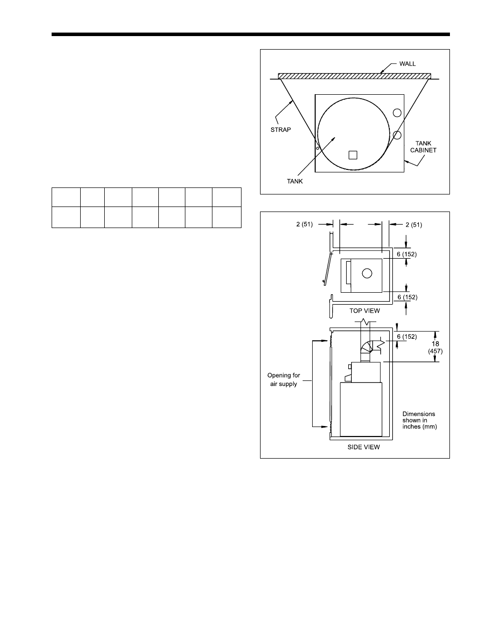
Figure 4. Installation in Closet.
water will not damage areas below the appliance.
If a suitable location can not be found, install a
drain pan under the appliance. Make sure the
drain pan is properly piped to an adequate drain.
2.
Place the water heater as close as possible to the
vent or chimney.
3.
For minimum clearances around the water heater,
refer to Table 2. Maintain the minimum distances
from all combustible surfaces (see Figure 4). The
unit can be installed in a closet. Pay special
attention to the air supply opening to the closet.
It is recommended that at least 12 inches
(305mm) is allowed around the entire unit for
maintenance, inspection, and plumbing access.
Left
Right
Side
Side
Rear
Front
Flue*
Top
inches
6
6
2
2
6
18
mm
152
152
51
51
152
457
*One inch (25 mm) clearance using type B double wall vent pipe
when vented vertically.
Table 2. Minimum Clearances from
Combustible Surfaces.
4.
This product may be installed on combustible
flooring. Do not install directly on carpeting.
5.
Be sure that the parts in the gas ignition system
are protected from water when the water heater is
operating or being serviced. Arrange water lines
in the area so that water cannot drip or spray
onto the water heater.
6.
If the product is to be installed in a location
where vibration or tipping is a concern, the unit
may be secured to a fixed vertical surface. The
TL80 is equipped with slots in the cabinet that
can accommodate a strap up to 1½" wide. To
secure the unit to a wall, place a strap around the
tank (not the tank enclosure), as shown in Figure
3. Allow the strap to pass through the slots
provided in the cabinet. Secure the strap as
necessary to the wall.
1H. Gas Supply Piping
Please review these instructions before installing
the water heater.
1.
Check that the water heater is fitted for the
proper type of gas by checking the rating plate.
2.
Laars water heaters are normally equipped to
operate below a 2000 foot altitude. Water heaters
equipped to operate at higher altitudes have
appropriate information on the rating plate.
Figure 3. Strap Location.
3.
Use the figures in Table 3 to provide adequate gas
piping from the gas meter to the water heater.
4.
A sediment trap (drip leg) must be provided
ahead of the gas controls (see Figure 5). A
manual gas shutoff valve must also be provided
for service, convenience and safety. This should
be installed about 5 feet (1.5 m) above the floor.
Check the local codes.
5.
Turn off the water heater before you do any
pressure testing on the gas lines.