LAARS Mighty-Stack TL80-199 - Installation, Operation and Maintenance Instructions User Manual
Page 11
Mighty Stack Water Heater
Page 11
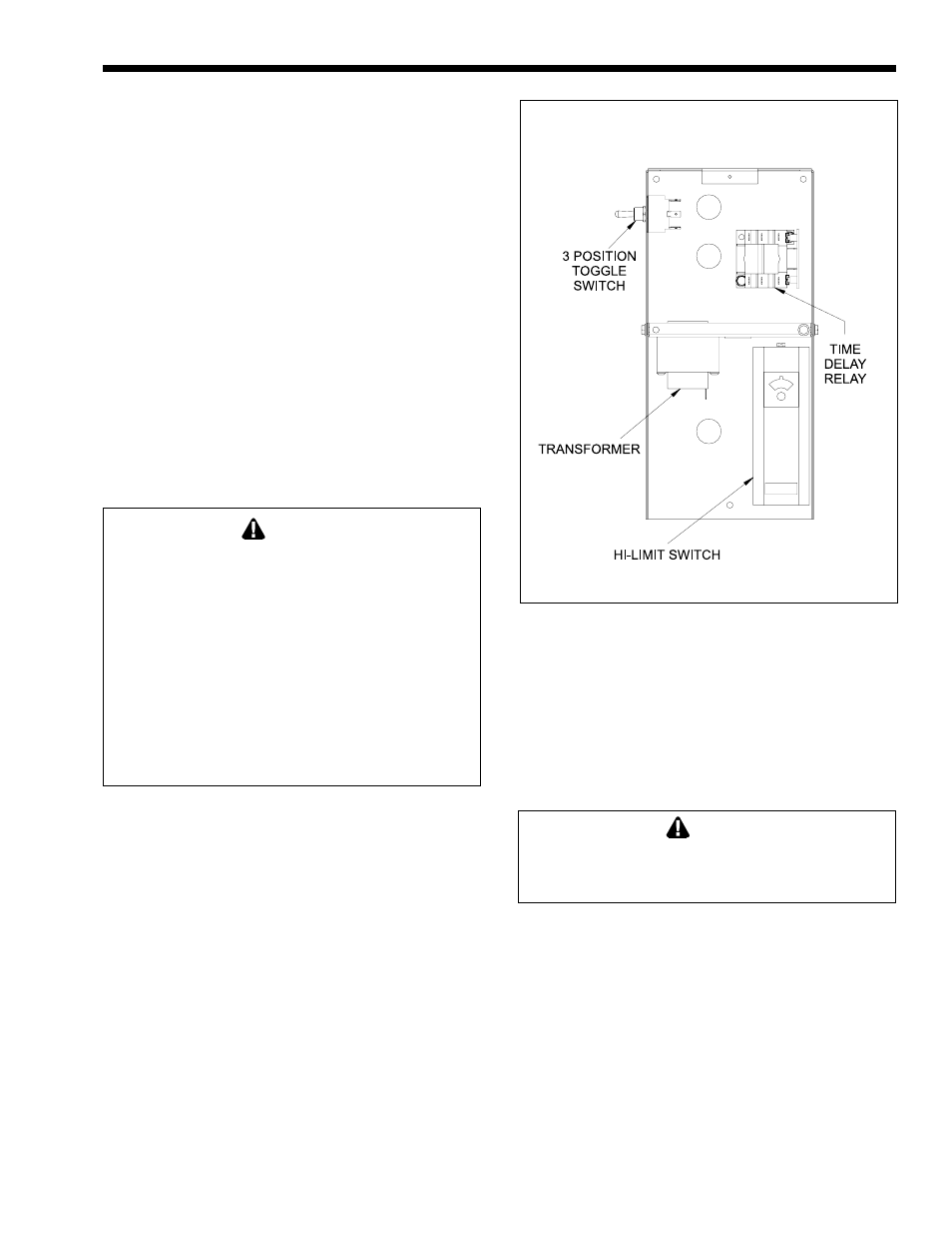
Figure 12. Location of Parts in Control Box.
NOTE: Ensure expansion tank pressure rating is
sufficient to withstand system operational pressure.
1N. Electrical Wiring
1.
Check the voltage, frequency, and phase of the
wiring to the water heater and pump. This unit is
designed to operate on 115V AC, 60 Hz, single
phase. (The controls and switches on this unit
operate on 24V AC. This voltage is produced by
a transformer and draws less than 12 amps.)
2.
A means of switching off 115V AC to the unit is
provided by a 3-position toggle switch on the
control panel (see Figure 12). Additional
switches or connections may be required by local
authority. If there are no local requirements,
follow the latest edition of the National Electrical
Code, ANSI/NFPA 70, in the U.S. In Canada,
follow the latest edition of CSA C22.1 Canadian
Electrical Code, Part 1.
WARNING
The boiler must be electrically grounded. Follow the
requirements of the local authority having
jurisdiction. In the absence of such requirements,
follow the latest edition of the National Electrical
Code ANSI/NFPA 70 in the U.S., or the latest
edition of CSA C22.1 Canadian Electrical Code,
Part 1, in Canada. Do not rely on the gas or water
piping to ground the metal parts of the boiler.
Plastic pipe or dielectric unions may isolate the
boiler electrically. Service and maintenance
personnel who work on or around the boiler may be
standing on wet floors, and could be electrocuted
by an ungrounded boiler.
3.
The 3-position switch is configured as follows:
Middle Position
All power to the unit is shut
off
‘Down’ Position Boiler On, pump in automatic
mode. the pump will shut off
3 minutes after the call for
heat is satisfied.
‘Up’ Position
Boiler On, pump in constant
on mode. The pump will
continue to run after the call
for heat is satisfied.
4.
To make the wiring connections, remove the two
screws which attach the front cover of the
control box.
5.
There are two sets of wires near the top of the
control box. These wires are for connection to
the 115V AC lines. Connect the hot lead from
the 115V power supply to the black wire.
Connect the three white wires to the neutral side
of the 115V line (see Figure 13).
1P. Filling the Storage Water Tank
Caution
Air must be removed from the heater and the tank
before the unit is operated. If this is not done, the
heat exchanger may be damaged.
1.
Open the hot water faucet(s) to allow air to escape.
2.
Open the shut-off valve(s) in the cold water
supply line.
3.
Open the shut-off valve(s) in the hot water
supply line.
4.
Turn off the gas to the unit, but allow the pump
to run for about 15 minutes. This will allow any
remaining air to collect in the top of the tank.
5.
Open the pressure relief valve to remove any
remaining air.
6.
Turn on the gas and check for leaks. Now the
unit is ready to operate.