Out of production – LAARS Mighty Max VW (Sizes 320M - 400M) - Installation, Operation and Maintenance Instructions User Manual
Page 5
Mighty Max Volume Water Heater
Page 5
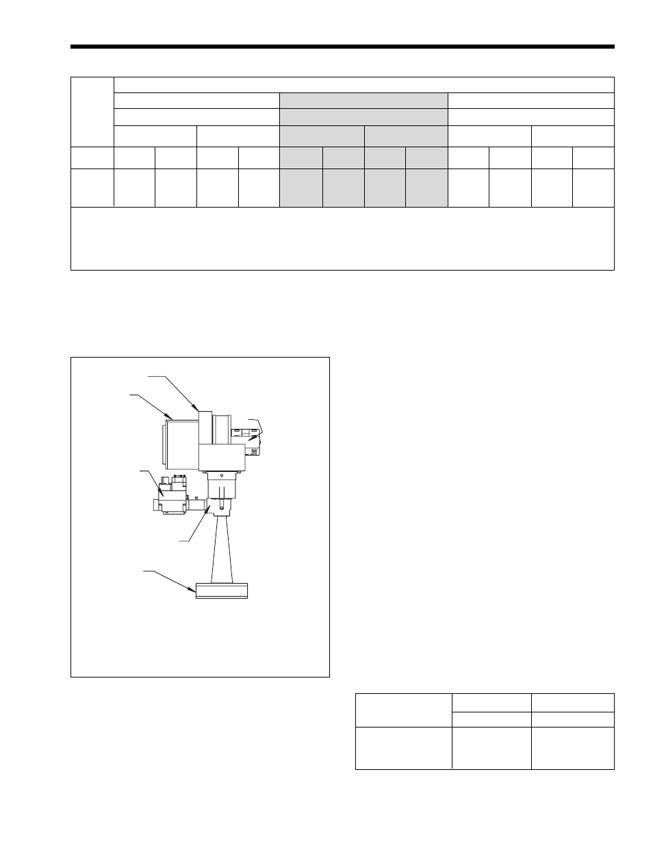
Figure 3. Heater Gas Valve Arrangement.
Notes: 1. These numbers are based on 1/2 inch (13mm) water column pressure drop.
2. Check supply pressure and local code requirements before proceeding with work.
3. Pipe fittings must be considered when determining gas pipe sizing.
Table 3. Natural Gas and Propane, Pipe Size Requirements.
SIZES:
320M, 400M
Venturi
Air Shutter
Enclosure
Automatic,
Regulator
and
Redundant
Gas Valve
Mixture
Plenum
Filter
Housing
Blower
Motor
NOTE: The above diagram is a representation, actual venturi
assembly may vary depending upon heater size.
2.6 Gas Supply and Piping
Review the following instructions before
continuing the installation.
1.
Gas piping installation must be in accordance
with the latest edition of ANSI Z223.1/NFPA 54.
In Canada, the installation must be in accordance
with CSA B149.1 and all local codes that apply
(see Figure 3 for heater gas valve arrangement).
2.
Check the rating plate to make sure the heater is
fitted for the type of gas being used. Laars
heaters are normally equipped to operate below a
2000 foot (610m) altitude. Heaters equipped to
operate at high altitudes have appropriate
stickers or tags attached.
3.
The figures in Table 3 should be used to size the
gas piping from the gas meter to the heater.
Check local codes for BTU/h capacity required.
4.
Install a sediment trap (drip leg) ahead of the gas
controls (see Figure 4). Fit the trap with a
threaded cap which can be removed for cleaning.
5.
When required by code, install a second manual
gas shutoff valve. Do not remove manual shutoff
valve supplied with the heater.
6.
Disconnect the heater and its individual shutoff
valve from the gas supply piping system during
pressure testing of the system at pressures higher
than 1/2 psi (3.5 kPa). Isolate the heater from the
gas supply piping system by closing its
individual manual gas shutoff valve during any
pressure testing of the gas supply piping system
at test pressures equal to or less than 1/2 psi
(3.5 kPa).
7.
Gas supply pressures to the heater are listed in
Table 4.
Supply Pressure
Natural Gas
Propane Gas
Water Column
in.
mm
in.
mm
Minimum
5
127
9
229
Maximum
9
229
14
356
Table 4. Gas Supply Pressure Requirements.
the top of the heater or the back, and combustion air
can be obtained from the room where the heater is
installed or ducted directly to the heater from outdoors
(see Sections 2.8 through 2.11 for details).
Distance from Gas Meter or Last Stage Regulator
0-100 feet
100-200 feet
200-300 feet
0-30m
30-60m
60-90m
Natural
Propane
Natural
Propane
Natural
Propane
Size
in.
mm
in.
mm
in.
mm
in.
mm
in.
mm
in.
mm
320M
1.25
32
1.25
32
1.50
38
1.25
32
1.50
38
1.50
38
400M
1.25
32
1.25
32
1.50
38
1.25
32
2.00
51
1.50
38
OUT OF
PRODUCTION