LAARS Pennant PNCP - Install and Operating Manual User Manual
Page 14
LAARS Heating Systems
Page 14
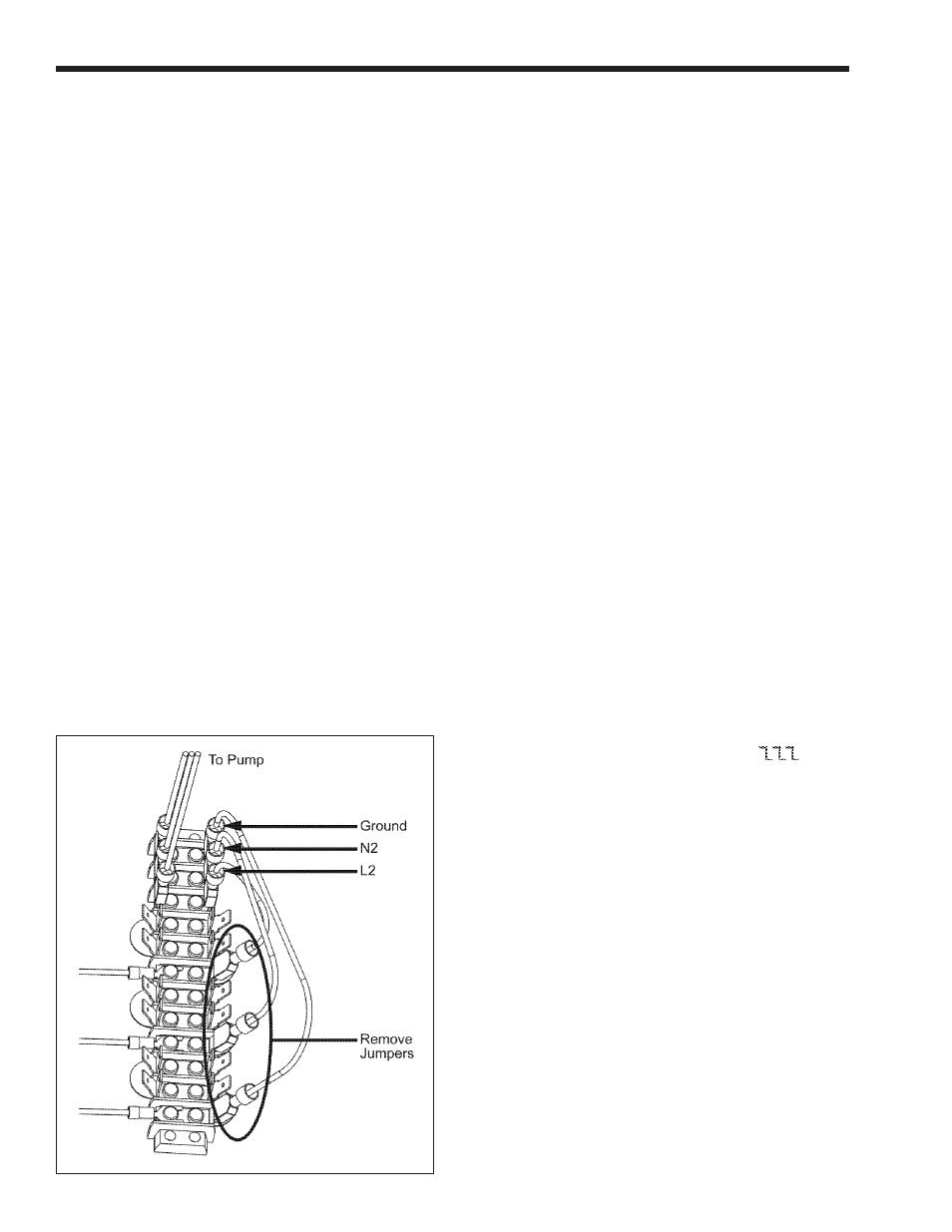
spade (fork) terminal. From the other side of the main
power switch connect to the main terminal block using
a ¼" female insulated quick connect. This will be
the same position where the jumper had terminated
(see Figure 7). Connect N2 and Ground to the main
terminal block using ¼" female insulated quick
connect (refer to Figure 7).
5.1.4 Auxiliary Time Clock Wiring
If a time clock is used to control the pool filter
pump operation, a separate switch or relay must be
used to shut off the heater at least 15 minutes before
the filter pump is shut off. A remote switch or relay,
if installed, should be connected across the “Other
Ints” terminals on the field-wiring terminal strip (see
Figure 9) after removing the factory-installed jumper
from those terminals. For manual shut off, a switch is
provided and identified with a label on the right side of
the heater.
All field-installed electrical safety devices and
controllers may also be connected across the Pennant’s
“Other Ints” terminals after the factory-installed
jumper is removed. If a remote switch or relay
(mentioned above) is installed, the other field-installed
electrical safety devices and controllers should be
wired in series with that switch or relay.
5.1.5 All Sizes
Wiring diagrams are shown in Section 10 in
Figures 13 through 17. Field wiring is shown in
Section 10 in Figure 18.
IMPORTANT NOTE: If the backwash operation is
manual the heater must be shut off manually during
backwashing.
5.2 Temperature (Operating) Control
The Pennant temperature control operates by
measuring the pool loop return temperature, before
the heater inlet piping. It is adjustable to a maximum
of 104° F and will prevent heater operation at return
temperatures above 104° F. It also controls the pool
heater pump and the temperature of the water entering
the heat exchanger. It also controls the Pennant pump
operation and the mixing system, which tempers the
water entering the heat exchanger to prevent damage
from condensation. The sensors for the control
are installed as shown in Figure 6 and Section 4.3,
Sensor Locations. The automatic mixing system
sensor, already installed, is shown in Figure 5. During
operation, the automatic mixing system diverts water
from the outlet to the inlet to “pre warm” the water to
a minimum inlet temperature of 120°F. This prevents
condensation from forming, which can damage the
heater.
5.3 Programming the Temperature
Control
5.3.1 Temperature Control Overview
The digital display on the control has the
following uses:
•
To display the actual pool loop temperature
during normal operating mode.
•
To allow the user to view and adjust the
control settings.
Figure 8 identifies the control buttons.
The Pool Heater Temperature Control face
contains an LCD screen and four (4) buttons (see
Figure 8). The LCD screen will display the pool loop
return temperature during normal operation. When
the control is first powered up, it displays
. It
then displays the temperature at the pool loop sensor.
After the temperature is displayed, the current settings
(parameters) may be viewed. To scroll through the
parameters, press the down arrow button to advance to
the next parameter.
5.3.2 Programming Control Parameters
There are four (4) control parameters that may
be set. They are the Pool Loop Temperature (LSP), the
Pool Loop Temperature Differential (dLS), the Boiler
Temperature (bsp) and the Pump Off Delay (Pd).
The pool loop temperature (desired pool
temp-erature) is set by changing the LSP parameter.
After scrolling through the parameters until LSP is
displayed, press the enter button. The setpoint will be
displayed. Press the up arrow or down arrow buttons
until the desired setpoint is displayed. Press the
enter button and the setpoint will be activated. The
display will return to indicating the present pool loop
temperature.
In addition to the ability to set the pool loop
temperature, the differential associated with that
setting may also be adjusted. The differential is set by
Figure 7. Removing Jumpers.