LAARS Mighty Therm VW (Sizes 2000-5000) - Installation, Operation and Maintenance Instructions User Manual
Page 7
Page 7
Mighty Therm Volume Water Heaters
Figure 5. T-Fitting Sediment Trap Installation.
2.
Use the figures in Table 3 to provide adequate
gas piping (check local code for BTU capacity
required). See Table 4.
3.
A trap (drip leg) must be provided ahead of the
gas controls (see Figure 5). Where required by
code, provide a second manual gas shutoff valve.
Do not remove manual valve furnished with the
heater.
4.
The heater and its individual shutoff valve must
be disconnected from the gas supply piping
system during any pressure testing of that system
at test pressures in excess of 1/2 psig. The heater
must be isolated from the gas supply piping
system by closing its individual manual gas
shutoff valve during any pressure testing of the
gas supply piping system at test pressures equal
to or less than 1/2 psig.
5.
Provide gas supply pressure to the heater as
follows:
Note: The heater and all other gas appliances
sharing the heater gas supply line must be firing at
maximum capacity to properly measure the inlet
supply pressure. Low gas pressure could be an
indication of an undersize gas meter and/or obstructed
gas supply line.
6.
The correct burner manifold gas pressure is
stamped on the rating plate. The regulator is pre-
set at the factory, and normally requires no
further adjustment.
7.
The gas manifold and control assembly was
tested and conform to the safe lighting and other
performance criteria specified in the latest
editions of ANSI Z21.13 and CGA 3.3 Low
Pressure Heater Standard.
8.
Before operating the heater, the complete gas
supply system and all connections must be tested
for leaks using a soap solution. Do not use raw
flame.
Caution
Since some leak test solutions, including soap and
water, may cause corrosion or stress cracking, the
piping must be rinsed with water after testing, unless
it has been determined that the leak test solution is
noncorrosive.
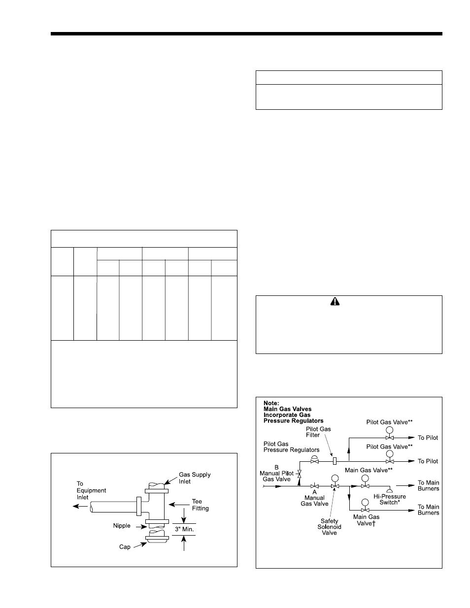
Arrangement of gas train components for on-off,
2-stage and 4-stage firing are shown schematically in
the Gas Piping Diagram (see Figure 6).
Distance from Gas Meter or Last Stage Regulator
0-100'
100-200'
200-300'
Nat.
LP
Nat.
LP
Nat.
LP
2000
––
2-1/2
2
3
2-1/2
3
3
2450
2200
3
2-1/2
3
2-1/2
3-1/2
3
3050
2800
3
2-1/2
3-1/2
3
3-1/2
3
3500
3200
3
2-1/2
3-1/2
3
4
3-1/2
4050
3600
3-1/2
3
4
3-1/2
4
3-1/2
4500
4000
3-1/2
3
4
3-1/2
5
4
5000
4500
4
3-1/2
4
3-1/2
5
4
NOTES:
These figures are based on 1/2" water column
pressure drop.
Check supply pressure and local code requirements
before proceeding with work.
Pipe fittings must be considered when determining gas
pipe sizing.
Table 3. Gas Line Selection Chart For
Natural and Propane Gas.
Indoor
Size
Outdoor
Size
Natural Gas
LPG
Min. (inches water column)
7
11
Max. (inches water column)
9
14
Figure 6. Typical Gas Piping Diagram.
*
Standard on sizes 3050-5000
** Sizes 2000 & 2450 use one pilot gas valve