LAARS Mighty Therm VW (Sizes 2000-5000) - Installation, Operation and Maintenance Instructions User Manual
Page 17
Page 17
Mighty Therm Volume Water Heaters
13.
Install front panel making sure opening for
removable panel is square. (19)
14.
Install front stiffener sizes 2450 and up.
15.
Install remaining screws from flue collector
extension.
16.
Install rear top half panel. (5)
17.
Install front top half panel. (6)
18.
Install front wire (26) mesh using angle (24) at
top and strap (25) at bottom (mesh to be inserted
under angles of wind baffle stand offs).
19.
Install rear mesh same as Step 18.
OUTDOOR KIT PARTS LIST (see Figure 17)
Key No.
Part No.
5 ................................................................... 20017100
6 ................................................................... 20016900
7 ................................................................... 20015101
..................................................................... 20015102
8 ................................................................... 20016700
9 ................................................................... 20017200
10 ................................................................. 20017300
11 ................................................................. 20017700
12 ................................................................. 20016500
13 ................................................................. 20016600
14 ................................................................. 20016300
15 ................................................................. 20014301
..................................................................... 20014302
16 ................................................................. 20015200
17 ................................................................. 20015300
18 ................................................................. 20014601
..................................................................... 20014602
19 ................................................................. 20016100
20 ................................................................. 20018000
21 ................................................................. 20016200
22 ................................................................. 20017200
23 ................................................................. 20017600
24 ................................................................. 20018200
25 ................................................................. 20018300
26 ................................................................. 20018600
27 ................................................................. 20015001
..................................................................... 20015002
28 ................................................................. 20016800
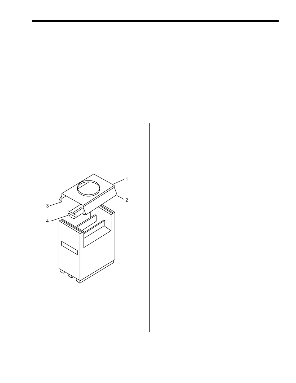
Figure 16. Removal of Indoor Parts.
20.
Install front LH & RH wind baffle stand off. (23)
21.
Install rear LH & RH wind baffle stand off. (23)
22.
Install front and rear wind baffles. (22)
23.
Install middle rear baffle stand off. (11)
24.
Install middle rear baffle. (10)
25.
Install wires control box parts onto control
panel. (200185)
26.
Install control panel assembly using holes and
bushings provided in RH extension panel for
probes and wires (not shown).
27.
Install removable panels. (20)