0 seating the comm board, 0 contact keri systems, Comm board – Keri Systems Comm Board User Manual
Page 3: Installation guide
Comm Board
Installation Guide
Page 3 of 3
P/N: 01216-002 Rev. C
2.0
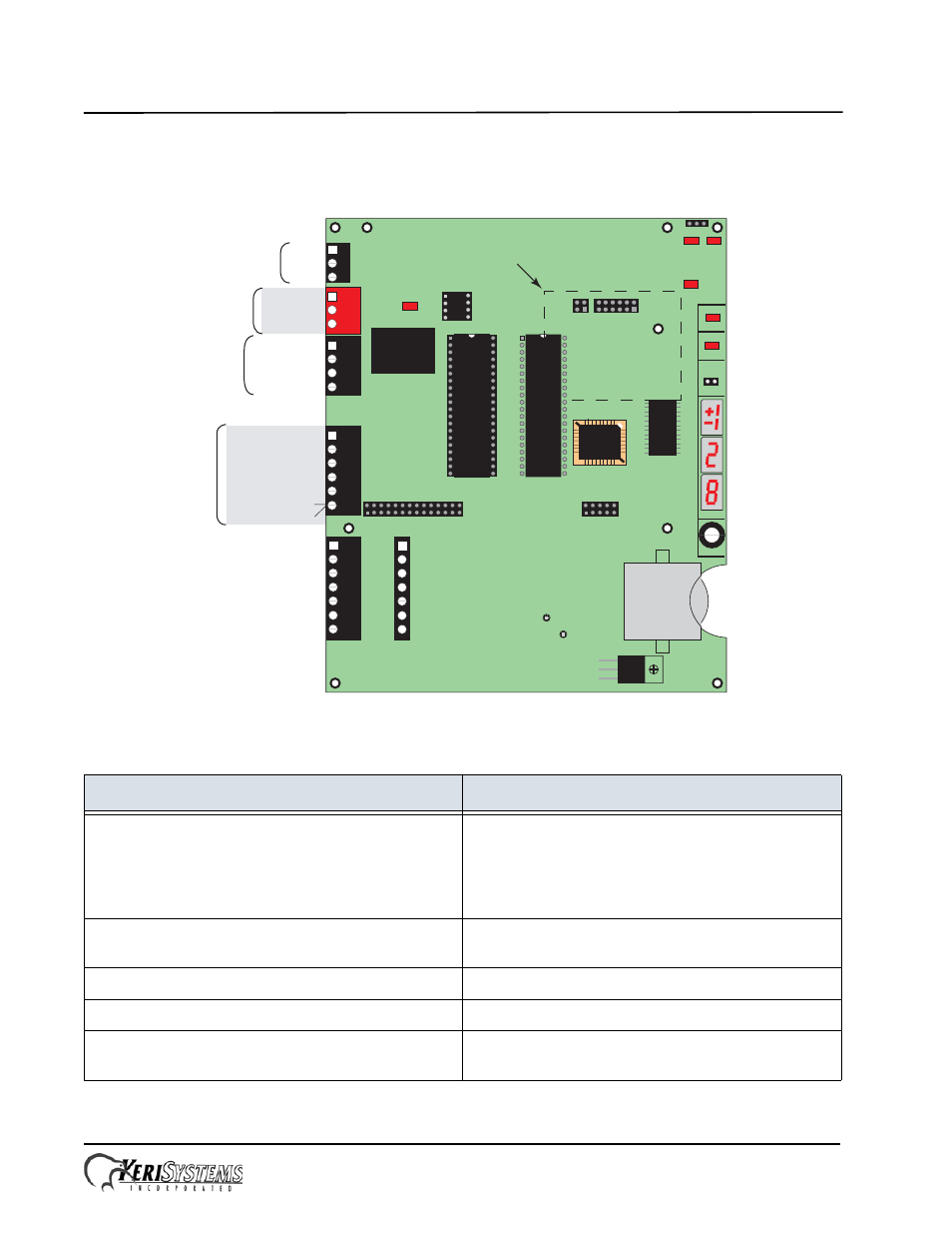
Seating the Comm Board
Seat the Comm Board into TB13 and TB14 as shown in the drawing below.
3.0
Contact Keri Systems
end of document
Keri USA
Keri UK, Ireland, Europe
2305 Bering Drive
San Jose, CA 95131
Unit 17
Park Farm Industrial Estate
Ermine Street
Buntingford
Herts SG9 9AZ UK
Telephone: (800) 260-5265
(408) 435-8400
Telephone: + 44 (0) 1763 273 243
Fax: (408) 577-1792
Fax:+ 44 (0) 1763 274 106
Web: www.kerisys.com
Web:www.kerisystems.co.uk
E-mail: [email protected]
E-mail:[email protected]
[email protected]
TB6
RS-485
Network
12 VDC
Power
Lock
Relay
Inputs
ADDRESS
POWER
NOISE
TP3
S1
LED 8
COMM
LED 9
TB1
GND
TP2
Reader Signal Strength
Test Points
TxRx -
TxRx +
Shield
+12 VDC
Negative
Earth Ground
Lock - NO
Lock - Common
Lock - NC
Door Switch - NC
Ground
RTE - NO
- not available -
Ground
Global Unlock - NO
Auxiliary RTE "A" - NO
Lithium
Battery
A-Reader
B-Reader
JP10
Satellite Board Connectors
FUSE
TB5
1
2
3
4
5
6
7
7
1
2
3
4
5
6
TB3
1
2
3
4
TB2
1
3
2
1
2
3
Comm Board / LAN
Connectors
LED 1
485
JP9
LED12
LED11
LED6
EPROM
LOCK
LINE1 LINE2
A & B Reader Wiring
(See Figure 2)
TB4
1
2
3
4
5
6
PIC - MIOP
Lock
Relay
- not available -
Seating Area for
Comm Board or LAN Unit
TB13
TB14