0 specifications, 1 nxt-4x4 dimensions, 2 power requirements – Keri Systems NXT 4x4 User Manual
Page 2: 3 current requirements at 12 vdc, 4 relay contact rating, 5 operating conditions, 6 cable options, Nxt 4x4, Installation guide
NXT 4x4
Installation Guide
Page 2 of 4
P/N: 01998-001 Rev. G
2.0
Specifications
2.1
NXT-4x4 Dimensions
•
4x4 PCB
-
5.25 inches tall by 3.10 inches wide by 1.00 inches deep, not including wiring connectors
-
13.33 cm by 7.87 cm by 2.54 cm
•
4x4 Enclosure
-
8.00 inches tall by 7.00 inches wide by 2.75 inches deep
-
20.32 cm by 17.78 cm by 6.98 cm
2.2
Power Requirements
•
10 to 14 VDC @ 0.5 A (maximum current draw for a fully loaded NXT-4x4)
2.3
Current Requirements at 12 VDC
•
250 mA max for each NXT-4x4
NOTE: If you are driving an electronic locking device (magnetic lock, door strike, etc.) using the same power supply as
the 4x4, ensure the power supply provides enough current to drive every device connected, including an adequate safety
margin.
2.4
Relay Contact Rating
•
1 A @ 24 VDC
2.5
Operating Conditions
•
32°F to 150°F (0°C to 60°C) – 0% to 90% Relative Humidity, non-condensing
2.6
Cable Options
RS-485 bus runs can daisy-chain together an NXT-4x4 and NXT-Reader on one line. The total cable run distance should
be less than 500 feet from the NXT controller for runs with 4x4s and less than 1,000 feet for Reader-only runs.
NOTE: Cable resistance causes a drop in voltage at the end of long cable runs. Ensure the appropriate power and current
for your device is available at the device at the end of the cable run. Heavier gauge cable reduces this affect.
NOTE: Keri does not recommend hot-plugging a Reader, RIM, or 4x4 into an NXT controller.
Remove power from the controller prior to connecting these devices.
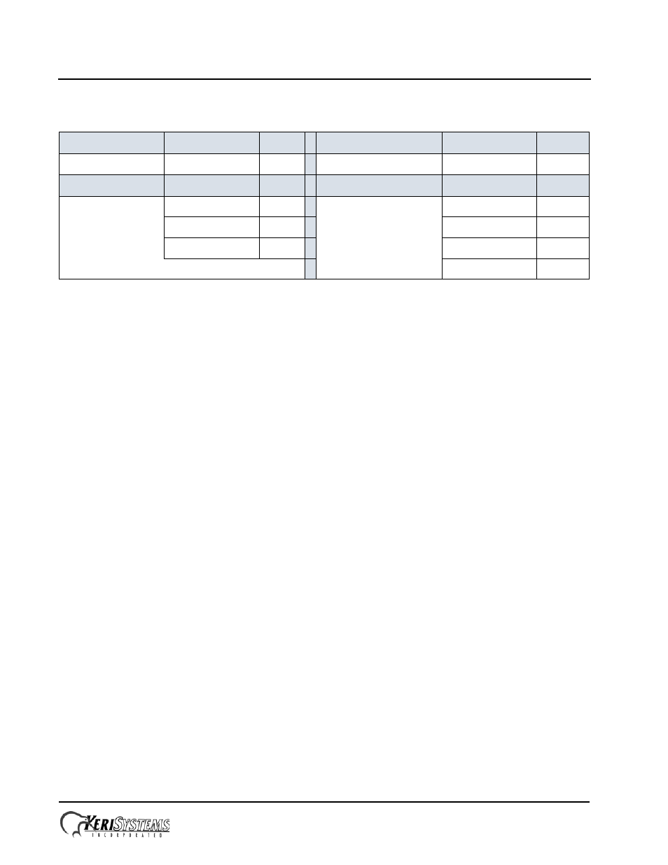
Table 1: 4x4 LEDs
Power
Purpose
LED
Future Application
Purpose
LED
indicator
a
undefined
b
Utility
Purpose
LED
Relay State
Purpose
LED
RS-485 Tx
c
Bus 1
f
User 1
d
Bus 2
g
User 2
e
Bus 3
h
Bus 4
i