Power door lock wiring, Jumper pin diagram – Crimestopper Security Products RS900/RS901 User Manual
Page 8
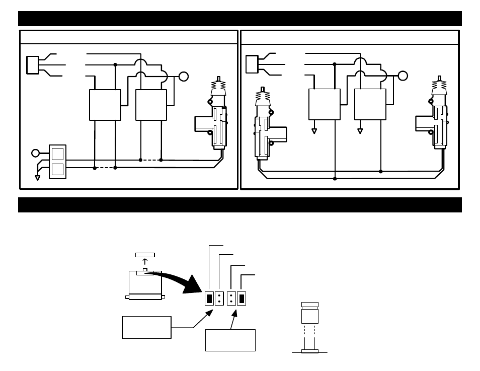
POWER DOOR LOCK WIRING
AFTERMARKET MOTOR/DOOR LOCK WIRING
REVERSE POLARITY DOOR LOCK WIRING
GREEN
GREEN
FUSED
FUSED
RED
RED
+12V
+12V
BLUE
BLUE
+
+
86
85
86
85
86
85
86
85
87
87
87
87
30
87A
30
87A
30
87A
30
87A
+
L
CUT
UL
CUT
MASTER
SWITCH
JUMPER PIN DIAGRAM
Jumper pins are used to change/configure the settings of the on board IGN2/ACC2 (PINK/WHITE) and the Parking Light (WHITE)
output relays. Snap open the door on the top of the control module to access these jumper pins.
JUMPER
PLUG
SIDE VIEW
JUMPER
PINS
JP1 JUMPERS:
IGN 2 OUTPUT (DEFAULT)
ACC 2 OUTPUT
(-) NEGATIVE PARKING LIGHT (500 mA)
+12V (10A) PARKING LIGHT (DEFAULT)
ON BOARD IGN2/
ACC2 RELAY
JP2 JUMPERS:
PARKING LIGHT
OUTPUT
CONTROL MODULE