Menu, Creen, Ontrols – Philips HD2528C User Manual
Page 7: Continued
Attention! The text in this document has been recognized automatically. To view the original document, you can use the "Original mode".
O
n
-S
creen
MENU
C
ontrols
(
continued
)
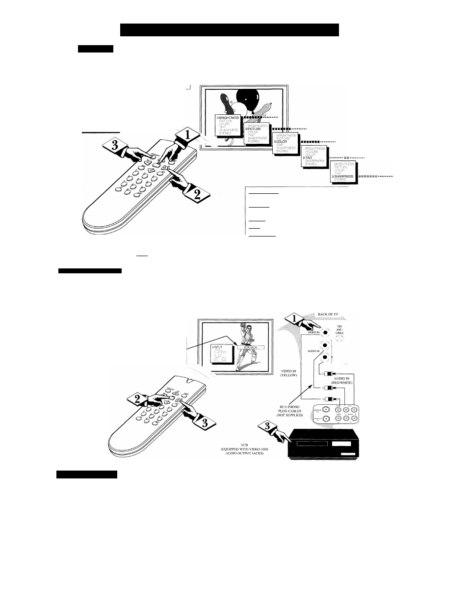
P
icture
J
'o adjust your TV picture
controls, select a channel
and follow the steps shown to
the right.
NOTE: The Smart Picture
control can automatically
adjust your TV's picture for a
variety of programs and
viev.nng conditions. See page
5 for details.
I-----i BEGIN)---------------------------
r<^ Press the MENU (M) |
button
on the remote, then
press the CH (+) or (-) (or
press MENU
A
or
T
button-
son the TV) until the desired
control shows on-screen.
Press the VOL (-r) and (-)
to adjust the selected picture
control.
Press
STATUS
button
(or
EXIT M enu) to clear the screen
when picture adjustments are
completed.
Remember, ^
with the bar scale
centered the control
settings are at normal
mid-range levels.
BRIGHTNESS
Press VOL (-) or (-f-) until darkest parts of the picture are
as bright as you prefer.
PICTURE
Press VOL (-) or (4-) until lightest parts of the picture show
good detail.
COLOR
Press VOL (-) or (-t-) to add or eliminate color.
TINT
Press VOL (-) or
(+)
to obtain natural skin tones.
SHARPNESS
Press VOL (-) or (+) to improve detail in the picture.
BEGIN)-
AuDioA^iDix) I
n pu t
J
a c k s
y
ou can view the playback
of VCR tapes (Video Disc
Players, camcorders, etc), by
using the AUDIO and
VIDEO INPUT jacks (on the
rear of the TV).
Connect the VIDEO
and AUDIO IN(put) jacks
on
the TV to the AUDIO and
VIDEO
OUT(put)
jacks on the
VCR.
Note:
Please be sure the
VCR’s (left, right) Audio
Output Jacks are matched to
the same Input Jacks on the TV.
Press the MENU (M) but
ton
on the remote, then the
CHANNEL
A
or ▼ buttons to
select the word
INPUT
with
the TV’s on-screen Arrow.
Press VOLUME (+) or (-)
buttons
to select the
VCR/AUX(iliary) INPUTS on the
rear of the TV.
l\irn the VCR ON
and PLAY the
VCR tape to be viewed on the TV.
PICTURE AND SOUND F-ROM
PLAYBACK OF VCR TAPE
NOTE: YOU CAN ALSO PRESS THE
CHANNEL
AT
BUTTONS TO
SELECT "VCR/AUX" (if it has been
added to the TV's channel memory. See
the "Add and Delete Channels" section
on page 4 for details.
Remember,
when you're
through using the
A/V INPUT jacks,
return the INPUT
display screen on
the TV to ANTEN
NA. If you leave
the TV in the
VCR/AUX INPUT
mode and there is
no signal source
connected to the
jacks, you will be
seeing only a blank
screen on the TV.
NOTE: If you have
a m ono (single
audio OUTPUT)
VCR, "Y"
Connectors are
available (from
your dealer or Parts
Information Center
1-800-851-8885)to
connect to the audio
inputs on the TV.
BACK OF VCR
G
lossary
Round Cable 75Q
* A single solid antenna wire normally matched with a metal plug
(F-type) end connector that screws (or pushes) directly onto a 75 Ohm input found on
the Television or VCR. (Also known as Coaxial Cable.)
Display
* An on screen message or graphics that help the user operate and adjust his
Television feature controls. See On Screen Displays (OSD).
Jack Panel
* Refers to the area on the back of the TV cabinet where the input and out
put connections are located.
On Screen Displays (OSD)
* Refers to the wording or messages generated by the tele
vision (or V CR) to help the user with specific feature controls (color adjustment, pro
gramming, etc.).
Menu
* An on-screen listing of feature controls shown on the Television screen that
are made available for user adjustments.
Programming
The procedure of adding or deleting channel numbers into the
Television’s m emory circuits. In'this way the Television “remembers” only the locally
available or desired channel numbers and skips over any unwanted channel numbers.
Remote Sensor Window
* A window or opening found on the Television control
panel through which infrared remote control command signals are received.
Status
* Allows the user to quickly confirm what channel number is currently being
viewed. Status can also be used to clear the Television of on screen displays or infor
mation (rather than waiting for the displays to “time out” or automatically disappear
from the screen).
Twin Lead Wire
* The more commonly used name for the two strand 300 Ohm anten
na w ire used with m any indoor and outdoor antenna systems. In m any cases this type
of antenna wire requires an additional adapter (or balun) in order to connect to the 75
Ohm Input terminals designed into the more recent Televisions and VCRs.
Volume Bar
* W hen in the ON position, this feature displays an on-screen display of
the TV’s volume setting.