Wiring wiring diagram renewal parts identification – Chromalox PF455-3 User Manual
Page 6
WIRING
WIRING DIAGRAM
RENEWAL PARTS IDENTIFICATION
1. Connect heater only to the voltage, frequency and phase spec-
ified on the nameplate.
2. All wiring should be done according to local and National
Electric Codes.
3. Make supply connections to marked heater terminals using
wire suitable for 75°C. (Type RH-RW or equivalent).
4. Conduit attachment to heater:
a. Run conduit(s) to conduit entrance plate. (See Figure 1).
b. Mark plate where conduit(s) will enter plate.
c. Remove screws and plate.
d. Punch conduit entrance plate with a hole(s) to accommo-
date the required conduit(s).
e. Reinstall plate and install conduit(s) to plate.
Fan Interlock. The fan circuit must be interlocked with the
control circuit of the heater. Refer to the wiring diagram in the
heater terminal box.
Hazard of electrical shock. Any installation involv-
ing electric heaters must be grounded to earth to
eliminate shock hazard.
Hazard of severe shock. Disconnect all power to
heater before servicing.
Control Ratings
Manual Limit Control
Automatic Limit Control
Pilot
Non-Inductive
Pilot
Non-Inductive
Volts
Duty
Rating
Duty
Rating
120
125 VA
3000 Watts
125 VA
3000 Watts
208
125 VA
5200 Watts
125 VA
5200 Watts
240
125 VA
6000 Watts
125 VA
6000 Watts
277
125 VA
6925 Watts
125 VA
6925 Watts
The appropriate wiring diagram
will be supplied with each heater.
Contact your local Chromalox Sales Office with Complete heater catalog number or part number.
-6-
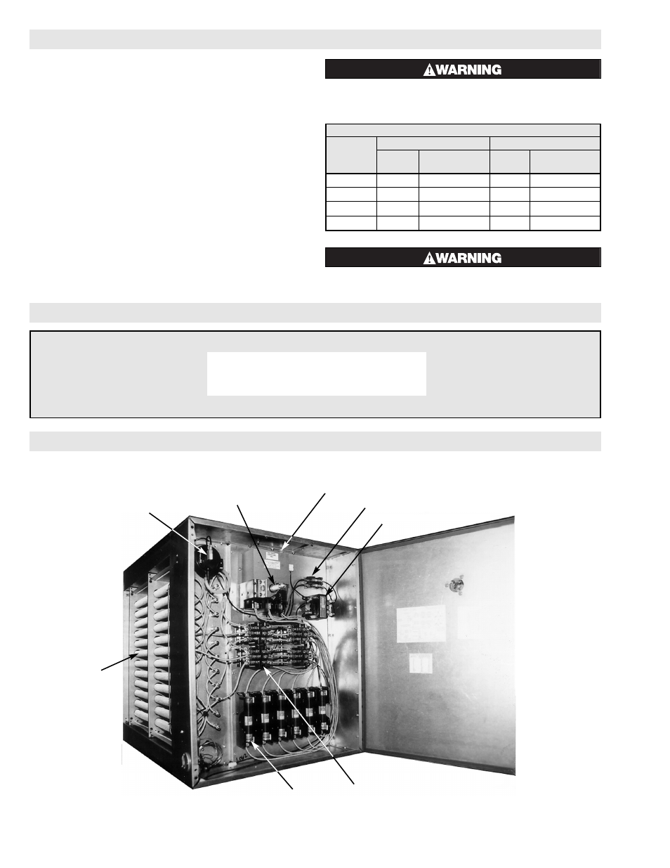
Static equalizers
(not shown) maintain
uniform air flow
across the heater
face when individual
fintubes are omitted.
Air Flow Switch
Main Disconnect
Conduit Entrance Plate
Contactor
Fusing
Air Flow Switch Automatic and Manual Reset
(not shown)
Fintube Heating
Element
Transformer Fusing
Transformer
Typical DHIF Duct Heater