Straight cable connection -9, Figure 3-6, F or details on how to obtain this document – Cabletron Systems 2H253-25R User Manual
Page 39: Rj21 screw screw, Led mode switch, Led mode switch in rx–tx position
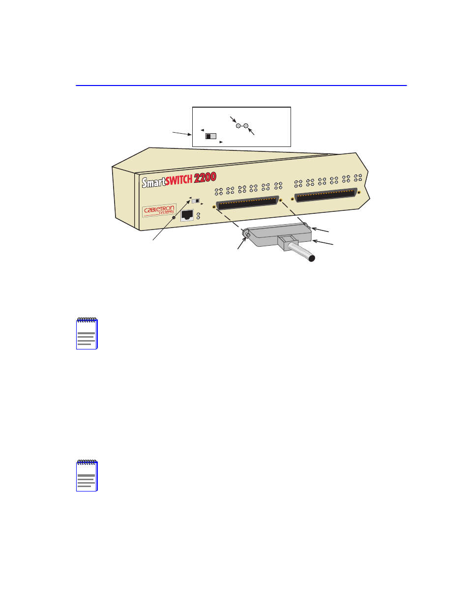
Connecting to the Network
Installation
3-9
Figure 3-6
Straight Cable Connection
3.
Tighten the two screws on the RJ21 straight cable connector to secure it to the device.
4.
Verify that a link exists on each twisted pair segment of the RJ21 connector by checking that
the associated port RX LED is on (flashing amber, blinking green, or solid green). If the RX
LED is off and the TX LED is not blinking amber, perform the following steps until it is on:
a.
Verify that the LED switch located near the COM port of the device is in the left-most
position (RX and TX LED indicators) as shown in
.
b.
Verify that the UTP cabling used is Category 3 (for 10BASE-T) or Category 5 (for
10BASE-T or 100BASE-TX). The Category 5 cabling must have an impedance of between
85 and 111 ohms.
NOTE
The cable pinouts for a 25-pair cable (RJ21) can be found in the Cabletron Systems
Cabling Guide. Refer to
for details on how to obtain this document.
NOTE
If a port is to operate at 10 and 100 Mbps, Category 5 cabling must be used. Refer to
for information about 100BASE-TX networks and cabling
.
2762-07
RJ21
Screw
Screw
FAST ETHERNET WORKGROUP
SWITCH
2H253-25R
COM
PWR
CPU
RESET
LED
MODE
RX-TX
DPX-SPD
1
2
3
4
5
6
7
8
9
10
11
12
13
14
13
15
16
17
18
19
20
21
22
23
24
LED MODE Switch
Receive (RX)
Transmit (TX)
LED
MODE
RX-TX
DPX-SPD
LED MODE Switch
in RX–TX position