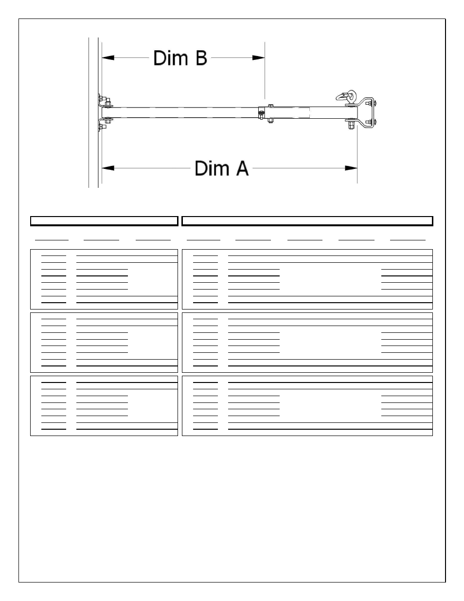
Figure 6: telescoping frame pipe insertion diagram – Jaypro Sports Stationary Backstops User Manual
Page 8
© 2009 Jaypro Sports Equipment JSL-Inst017 Rev D2 10-23-2009
8 of 16
Figure 6: Telescoping Frame Pipe Insertion Diagram
Upper Frame
Upper Frame
Upper Frame
Lower Frame
Frame Length
Exposed Pipe
Frame Length
Exposed Pipe
Frame Length
Exposed Pipe
(Dim A, Fig 6)
(Dim B, Fig 6)
(Dim A, Fig 6)
(Dim B, Fig 6)
(Dim A, Fig 6)
(Dim B, Fig 6)
48
41 1/4
2 1/4
48
42 1/8
3 1/8
40 1/2
1 1/2
49
42 1/4
3 1/4
49
43 1/8
4 1/8
41 1/2
2 1/2
:
:
:
:
:
:
:
:
:
:
:
:
:
:
:
:
:
:
:
:
:
:
:
:
:
71
64 1/4
25 1/4
71
65 1/8
26 1/8
63 1/2
24 1/2
72
65 1/4
26 1/4
72
66 1/8
27 1/8
64 1/2
25 1/2
72
65 1/4
2 3/4
72
66 1/8
3 5/8
64 1/2
2
73
66 1/4
3 3/4
73
67 1/8
4 5/8
65 1/2
3
:
:
:
:
:
:
:
:
:
:
:
:
:
:
:
:
:
:
:
:
:
:
:
:
:
95
88 1/4
25 3/4
95
89 1/8
26 5/8
87 1/2
25
96
89 1/4
26 3/4
96
90 1/8
27 5/8
88 1/2
26
96
89 1/4
2 3/4
96
90 1/8
49 5/8
134 1/2
2
97
90 1/4
3 3/4
97
91 1/8
50 5/8
135 1/2
3
:
:
:
:
:
:
:
:
:
:
:
:
:
:
:
:
:
:
:
:
:
:
:
:
:
143
136 1/4
49 3/4
143
137 1/8
50 5/8
135 1/2
49
144
137 1/4
50 3/4
144
138 1/8
51 5/8
136 1/2
50
GLASS BACKBOARD
Face of Bank
FAN ALUMINUM BACKBOARD
M
o
d
e
l
S
T
8
1
2
G
B
M
o
d
e
l
S
T
8
1
2
F
A
B
T
Add 1" for each
additional 1" Face
of Bank
Add 1" for each additional 1" Face of
Bank
Add 1" for each additional 1" Face of
Bank
Add 1" for each additional 1" Face of
Bank
Face of Bank
M
o
d
e
l
S
T
4
6
G
B
M
o
d
e
l
S
T
4
6
F
A
B
T
Add 1" for each
additional 1" Face
of Bank
M
o
d
e
l
S
T
6
8
G
B
M
o
d
e
l
S
T
6
8
F
A
B
T
Add 1" for each
additional 1" Face
of Bank
Figure 7: 48”-144” Telescoping Frame Pipe Lengths
e. Attach the board mount fittings to the end of the 1.90” pipe, using supplied eyebolts to build 2
of them. These will support the weight of the unit via the chains. The other two brackets use the
hex head bolts. Consult assembly diagrams for proper location of hardware.
f. For units less than 48” Face of Bank, some cutting of pipe may be necessary.
g. Measure this distance from the drilled end of the inner tube and place brace band accordingly.
a. For the Glass backboard, build all four (4) pipes the same way.
b. For the Aluminum Fan backboard, the top pipes differ from the bottom pipes by 1 5/8”.