Jaypro Sports Stationary Backstops User Manual
Page 10
© 2009 Jaypro Sports Equipment JSL-Inst017 Rev D2 10-23-2009
10 of 16
b. For units 4’-6’, a single brace is used. Center the brace pipe on the wall mount frame,
approximate location should be half the distance from the wall to the Face of Bank.
c. Over 6’ and two (2) braces are required on each frame set. First brace pipe should be
located at approximately 1/3 the distance from wall to face of bank. This may be
adjusted as needed so that this brace is attached to the 1.90” outer pipe – clamps will not
tighten if attached to the exposed portion of the inner 1.66” frame pipe. Second brace
pipe should be centered within the remaining distance between first brace to the
backboard.
t. Verify Face of Bank for unit – measure from face of wall to the playing surface of backboard.
Adjust brace bands on frame pipes as necessary. Once this has been accurately adjusted, drill
holes through inner 1.66” frame pipes (use existing hole in 1.90” outer frame pipe as your
guide). Secure frame pipes together permanently using hex bolt supplied. Remove brace bands.
Important! Frame pipes must be drilled as specified and permanently secured together with hex bolts.
Failure to follow these instructions correctly can result in collapse of frame, and possible injury.
u. Remove lifting mechanism.
v. Attach the goal loosely using the bolts provided and level from side to side while tightening.
w. Check height at the top of the goal – 10’ above the playing surface.
x. Final check all fittings and hardware to make sure everything is tight.
y. Attach edge padding if applicable.
Note:
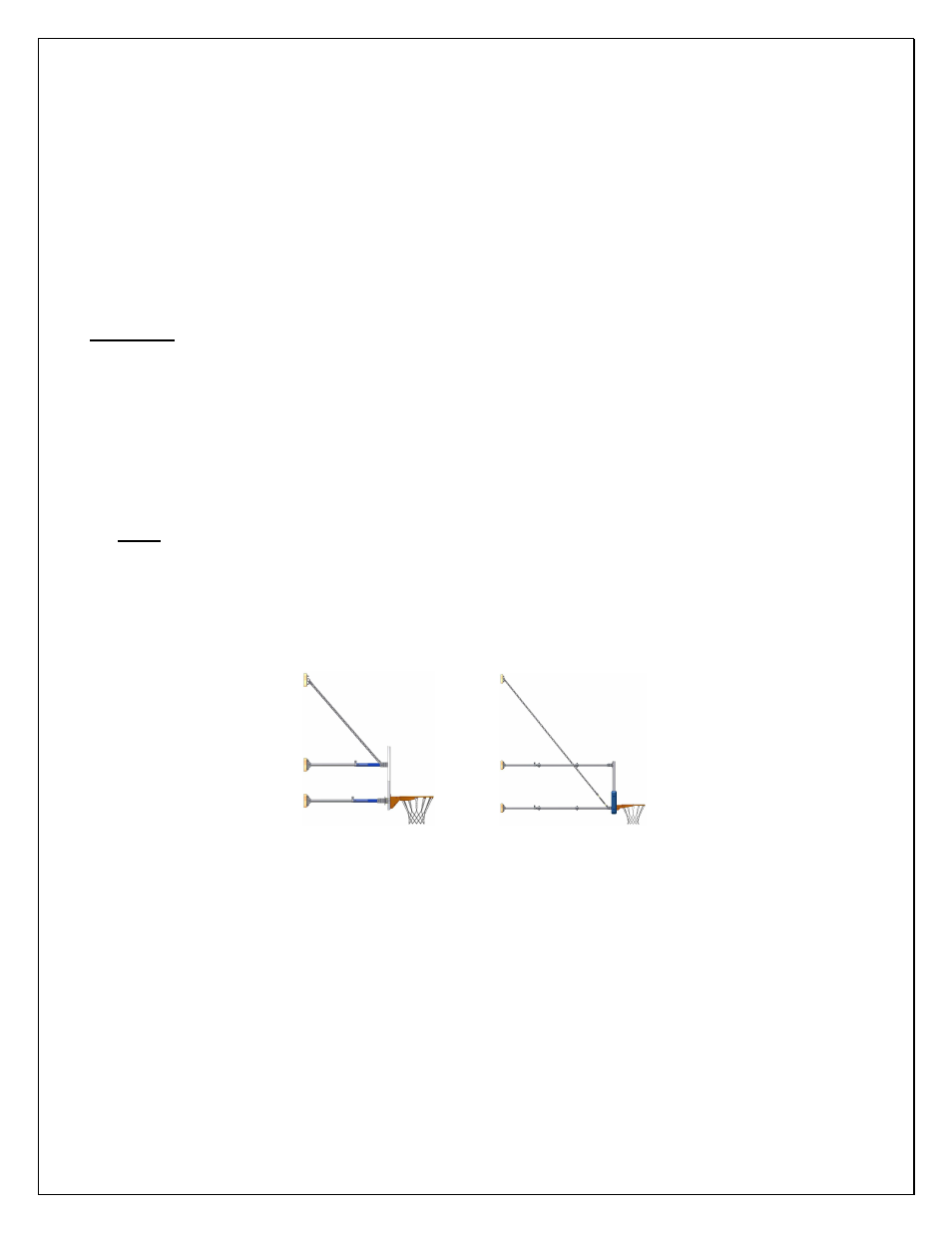
Chains may be optionally connected to bottom backboard mount brackets. In some assembly
diagrams, chains are shown at the top board mount brackets. Either design is acceptable, although
using the bottom board mount brackets will allow for lower wall attachment points for support
chains. This is helpful for larger units, when there are obstructions on the wall, or the wall height is
shorter than the top attachment design will allow for.
Figure 9: Top vs. Bottom Chain Attachment