Rs-485 headers (p5, p6), External power connector (p8), Table 6: rs-485 port 1 pinout (p5) – Connect Tech 104 User Manual
Page 10: Table 7: rs-485 port 2 pinout (p6), Table 8: external power connector pinout (p8), Figure 3: external power connection
Connect Tech FreeForm/PCI-104 User Manual
Revision 0.00
10
RS-485 Headers (P5, P6)
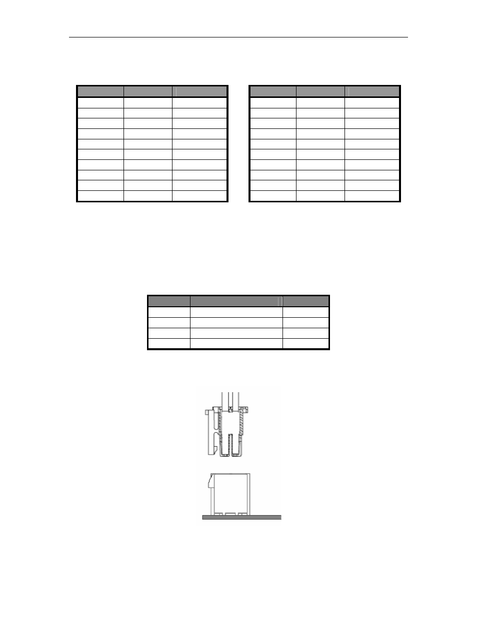
Table 6: RS-485 Port 1 Pinout (P5)
Pin
Signal
Direction
1
RXD+1
Input
2
3
RXD-1
Input
4
5
TXD+1
Output
6
7
TXD-1
Output
8
9
GND
power
10
Table 7: RS-485 Port 2 Pinout (P6)
Pin
Signal
Direction
1
RXD+2
Input
2
3
RXD-2
Input
4
5
TXD+2
Output
6
7
TXD-2
Output
8
9
GND
power
10
External Power Connector (P8)
The external connector provides 5V to the power regulation circuitry. In addition, the power
connector enables the 3.3V regulator and provides VIO to the PCI Bridge.
The external power connector should only be used when the FreeForm/PCI-104 is being
programmed out side of a PCI / PCI-104 system.
Table 8: External Power Connector Pinout (P8)
Pin
Signal
Direction
1
5V
Power
2
3.3 enable (connect to 5V)
Input
3
VIO (connect to 5V)
Power
4
GND
Power
It is recommended that a Connect Tech Inc. FreeForm/PCI-104 power supply is used. Orientation
of the power supply connector is important. Ensure that the clip on the cable aligns with the catch
on P8, as shown below.
Figure 3: External Power Connection