50pg03 – Carrier 50PG03-07 User Manual
Page 16
16
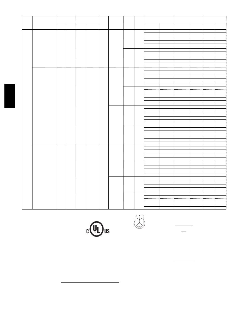
Table 2 -- Electrical Data -- Units Without Optional Convenience Outlet (cont)
UNIT
50PG
NOMINAL
POWER SUPPLY
Volts-Ph-Hz
VOLTAGE
RANGE
COMPRESSOR
OFM
FLA
POWER
EXHAUST
FLA
IFM
TYPE
IFM
FLA
ELECTRIC HEAT
POWER SUPPLY
DISCONNECT
SIZE
Min
Max
RLA
LRA
FLA
Nominal
kW*
MCA
MOCP†
FLA
LRA
07
(cont)
208/230-3-60
187
253
20.5
149
1.5
1.4
Low
5.2
—
—
33.7/33.7
35/35
33/33
184/184
10.0/11.5
3.8/ 5.0
33.7/33.7
35/35
33/33
184/184
15.0/17.3
5.6/ 7.5
33.7/33.7
35/35
33/33
184/184
20.0/23.1
7.5/10.0
33.7/37.1
35/40
33/34
184/184
30.0/34.6
11.3/15.0
45.8/51.5
50/60
42/47
184/184
40.0/46.2
15.0/20.0
58.3/66.0
60/70
54/61
184/184
50.0/57.7
18.8/25.0
70.8/80.4
80/90
65/74
184/184
High
7.5
—
—
36.0/36.0
40/40
36/36
210/210
10.0/11.5
3.8/ 5.0
36.0/36.0
40/40
36/36
210/210
15.0/17.3
5.6/ 7.5
36.0/36.0
40/40
36/36
210/210
20.0/23.1
7.5/10.0
36.1/40.0
40/45
36/37
210/210
30.0/34.6
11.3/15.0
48.6/54.4
50/60
45/50
210/210
40.0/46.2
15.0/20.0
61.1/68.9
70/70
56/63
210/210
50.0/57.7
18.8/25.0
73.6/83.3
80/90
68/77
210/210
460-3-60
414
506
9.6
75
0.8
—
Low
2.6
—
—
15.4
20
15
92
5.8
5.0
15.4
20
15
92
8.7
7.5
15.4
20
15
92
11.5
10.0
17.6
20
16
92
17.3
15.0
24.9
25
23
92
23.1
20.0
32.1
35
30
92
28.9
25.0
39.4
40
36
92
High
3.4
—
—
16.2
20
16
105
5.8
5.0
16.2
20
16
105
8.7
7.5
16.2
20
16
105
11.5
10.0
18.6
20
17
105
17.3
15.0
25.9
30
24
105
23.1
20.0
33.1
35
30
105
28.9
25.0
40.4
45
37
105
0.6
Low
2.6
—
—
16.0
20
16
93
5.8
5.0
16.0
20
16
93
8.7
7.5
16.0
20
16
93
11.5
10.0
18.4
20
17
93
17.3
15.0
25.6
30
24
93
23.1
20.0
32.9
35
30
93
28.9
25.0
40.1
45
37
93
High
3.4
—
—
16.8
20
17
106
5.8
5.0
16.8
20
17
106
8.7
7.5
16.8
20
17
106
11.5
10.0
19.4
20
18
106
17.3
15.0
26.6
30
24
106
23.1
20.0
33.9
35
31
106
28.9
25.0
41.1
45
38
106
575-3-60
518
633
7.6
54
0.8
—
Low
2.0
—
—
12.3
15
12
67
9.2
10.0
14.0
15
13
67
13.9
15.0
19.9
20
18
67
18.5
20.0
25.6
30
24
67
23.1
25.0
31.4
35
29
67
27.7
30.0
37.1
40
34
67
High
2.8
—
—
13.1
15
13
78
9.2
10.0
15.0
15
14
78
13.9
15.0
20.9
25
19
78
18.5
20.0
26.6
30
24
78
23.1
25.0
32.4
35
30
78
27.7
30.0
38.1
40
35
78
1.4
Low
2.0
—
—
13.7
15
14
69
9.2
10.0
15.8
20
14
69
13.9
15.0
21.6
25
20
69
18.5
20.0
27.4
30
25
69
23.1
25.0
33.1
35
30
69
27.7
30.0
38.9
40
36
69
High
2.8
—
—
14.5
15
14
80
9.2
10.0
16.8
20
15
80
13.9
15.0
22.6
25
21
80
18.5
20.0
28.4
30
26
80
23.1
25.0
34.1
35
31
80
27.7
30.0
39.9
40
37
80
LEGEND
FLA
--- Full Load Amps
HACR --- Heating, Air Conditioning and Refrigeration
IFM
--- Indoor (Evaporator) Fan Motor
LRA
--- Locked Rotor Amps
MCA --- Minimum Circuit Amps
MOCP --- Maximum Overcurrent Protection
NEC
--- National Electrical Code
OFM --- Outdoor (Condenser) Fan Motor
RLA
--- Rated Load Amps
*Heater capacity (kW) is based on heater voltage of 208v, 240v, 480v, or 600v. If power
distribution voltage to unit varies from rated heater voltage, heater kW will vary accord-
ingly.
{
Fuse or HACR circuit breaker.
NOTES:
1. In compliance with NEC requirements for multimotor and combination load equipment (refer
to NEC Articles 430 and 440), the overcurrent protective device for the unit shall be fuse or
HACR breaker. Canadian units may be fuse or circuit breaker.
2.
Unbalanced 3-Phase Supply Voltage
Never operate a motor where a phase imbalance in supply voltage is greater than 2%. Use
the following formula to determine the percentage of voltage imbalance.
% Voltage Imbalance
= 100 x
max voltage deviation from average voltage
average voltage
Example: Supply voltage is 230---3---60
AB = 224 v
BC = 231 v
AC = 226 v
Average Voltage = 224 + 231 + 226
3
681
3
=
227
=
Determine maximum deviation from average voltage.
(AB) 227 – 224 = 3 v
(BC) 231 – 227 = 4 v
(AC) 227 – 226 = 1 v
Maximum deviation is 4 v.
Determine percent of voltage imbalance.
% Voltage Imbalance
= 100 x
4
227
= 1.76%
This amount of phase imbalance is satisfactory as it is below the maximum allowable 2%.
IMPORTANT: If the supply voltage phase imbalance is more than 2%, contact your local electric
utility company immediately.
50PG03
--
07