Wiring the touchpad to the panel, Attaching the touchpad to the mounting plate, Power up and bus communication – Interlogix ATP1000 User Manual
Page 2: Programming
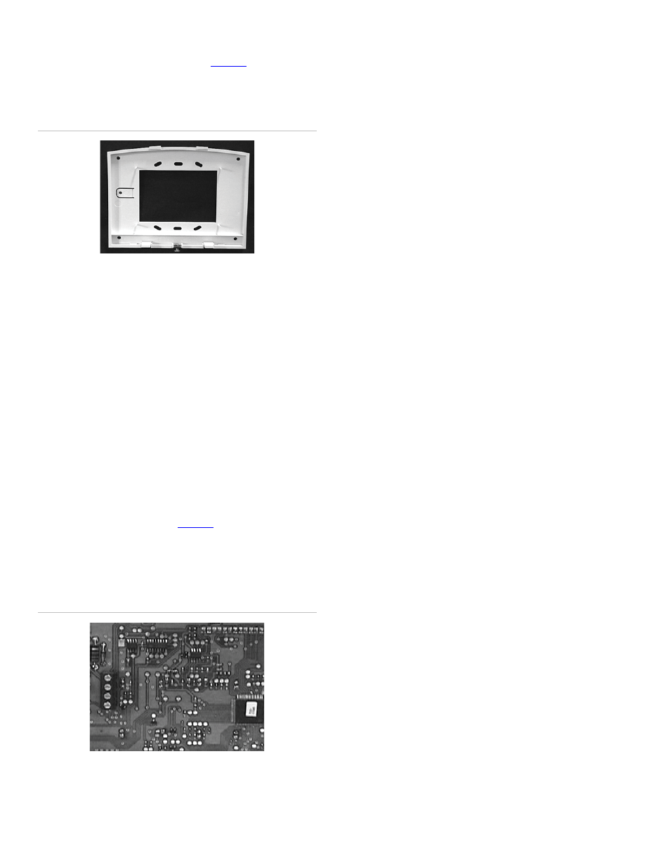
2. For wall mounting, place the mounting plate on the wall
and mark the mounting holes (see
). Be sure to
leave a 3-inch clearance below for the touchpad door to
open.
Figure 2. Mounting hole locations
Mounting Holes
Mounting Holes
3. Insert anchors into the wall at the marked locations where
studs are not present.
4. Align the mounting plate holes with the wall or gang box
screw holes and secure the back plate using the screws
provided.
Note: Do not over tighten screws or the mounting plate
may bind and prevent the touchpad from mounting
properly.
5. For wall-mount installations, cut a hole in the wall in the
wire access area of the mounting plate to pull the wiring
cable through.
Wiring the Touchpad to the Panel
1. Remove panel AC and backup battery power.
2. Run a 4-conductor, 18- to 22-gauge wire from the panel to
the touchpad location (see
3. Connect the touchpad +12V, BUS A, BUS B, and GND
terminals to the matching panel terminals (see Figure 3 for
touchpad terminal identification)
Figure 3. Touchpad wiring connections
GND
BUS B
BUS A
+12V
Attaching the Touchpad to the Mounting Plate
Align the tabs at the top of the mounting plate with the slots on
the touchpad and swing the touchpad bottom toward the
mounting plate. Gently tighten the screw into the bottom of the
touchpad.
Power up and Bus communication
After making all wiring connections from the touchpad to the
panel, you are ready to power up the panel and verify correct
communication between the touchpad and the panel. Upon
power up, the panel scans the bus for connected devices,
assigns a unit number to each bus device, and automatically
learns the device ID number of each bus device.
1. Verify that all wiring between the panel and touchpad is
correct.
2. Connect the panel battery and restore AC power.
Alphanumeric touchpads briefly show SCANNING BUS
DEVICES, then display date and time.
Note: Steps 3 through 9 are optional.
3. At the touchpad, enter program mode by pressing 8 +
installer/dealer code (default = 4321) + 0 + 0. The
touchpad should display SYSTEM PROGRAMMING.
4. Press É and the display shows SECURITY.
5. Press A or B until the display shows ACCESSORY
MODULES, then press É. The display should read BUS
DEVICES.
6. Press É. The display shows the lowest device address
and its ID. The following example shows what a device
address display may look like:
UNIT - ID
0—02110185*
*The 8-digit SuperBus ID number is also located on a label
on back of the touchpad.
7. Press A or B to cycle through all bus device addresses
until the touchpad appears.
8. After verifying the touchpad device ID, press Ç repeatedly
until the display shows SYSTEM PROGRAMMING.
9. Press A or B until the display shows EXIT
PROGRAMMING READY, then press É. The touchpad
should show the date and time display.
Programming
To program options for the newly installed touchpad (such as
key beeps) see the specific panel installation instructions.
2
ATP1000 Touchpad/Display Installation Instructions