Interlogix NX-4 User Manual
Page 37
NX-4 Control
Page 35
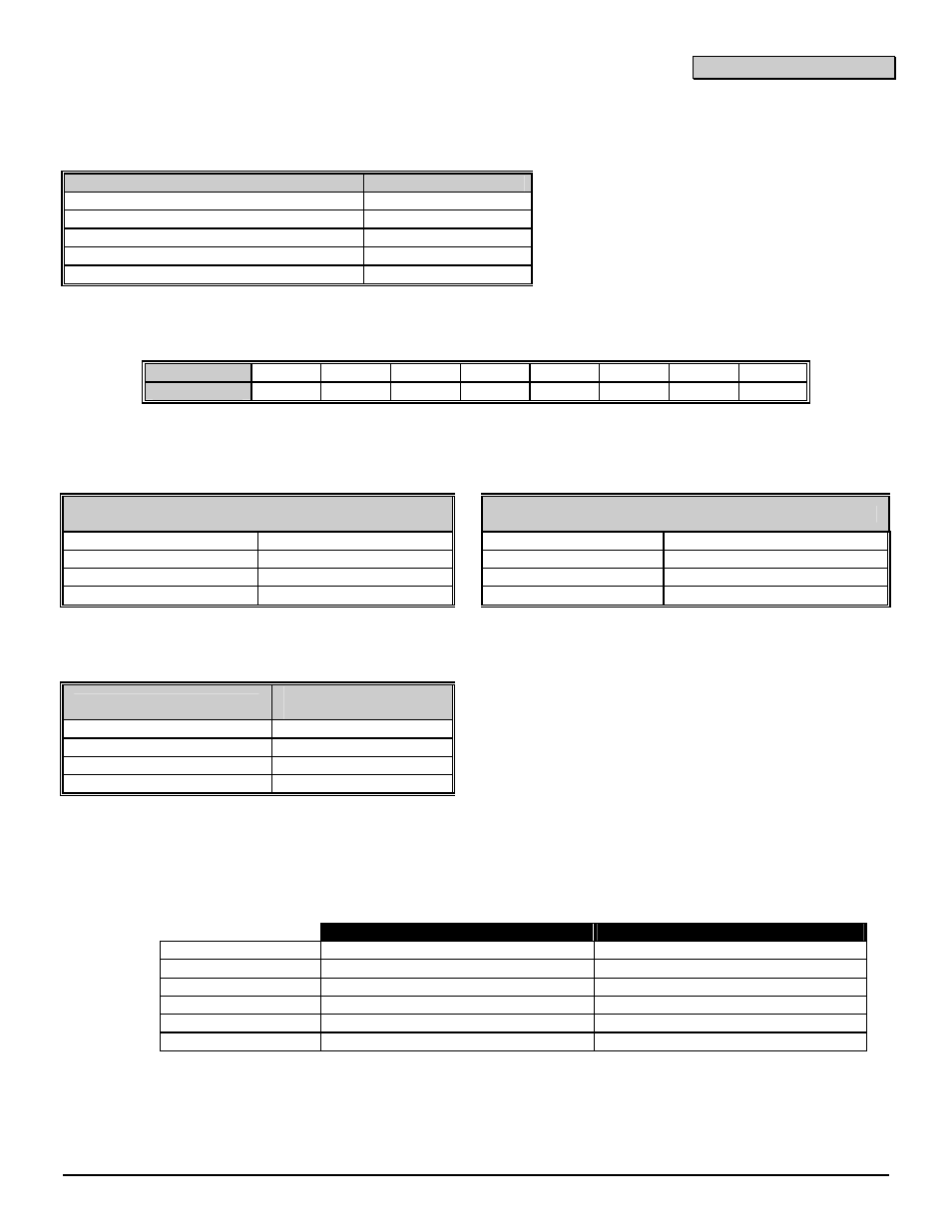
APPENDIX 3 EXPANDER NUMBERS FOR REPORTING EXPANDER TROUBLE
The tables below list the device numbers that will be reported for trouble conditions.
Device
Device # reported
NX-4 Control Panel
0
See pages 33 - 34 for possible report codes.
NX-534E Two Way Listen-In
64
NX-540E
AOperator@
40
NX-582E AES Interface
77
NX-591E Cellemetry Interface
76
KEYPADS
Keypad
1 2 3 4 5 6 7 8
Device #
192 200 208 216 224 232 240 248
REMOTE POWER SUPPLY (NX-320E)
OUTPUT
MODULE (NX-508E)
Address & Dip Switch Setting
Address & Dip Switch Setting
84 (All switches off) 88 (Switch 3 on)
24 (Switch 1 & 2 on)
28 (Switch 1,2,&3 on)
85 (Switch 1 on)
89 (Switch 1 & 3 on)
25 (Switch 3 on)
29 (All switches off)
86 (Switch 2 on)
90 (Switch 2 & 3 on)
26 (Switch 1 & 3 on)
30 (Switch 1 on)
87 (Switch 1 & 2 on)
91 (All switches on)
27 (Switch 2 & 3 on)
31 (Switch 2 on)
WIRELESS RECEIVER (NX-448E)
Switch Setting
Expander #
reported
All switches off
35
Switch 1 on
32
Switch 2 on
33
Switch 1 & 2 on
34
KEYPAD MAXIMUM WIRE RUN
(Note: These numbers are for one keypad at the end of the wire. When connecting more than one keypad to the end of
the wire, a higher gauge wire will be required.)
WHEN CONNECTED TO NX-4
WHEN CONNECTED TO NX-320E
Length in feet
Wire Gauge
Wire Gauge
250 24
22
500 20
18
1000 18
16
1500 16
14
2500 14
12