Powered device (pd) installation, Powered device (pd) installation 5 – Interlogix POE201-EX User Manual
Page 11
IFS POE201-EX POE Extender User Manual 5
2. The PSE delivers both Ethernet Data and PoE power over
the UTP cable to the POE201-EX and the “PoE IN” LED
will be illuminated.
Note:
The POE IN LED illuminates in a steady state to
indicate that it is receiving power.
If the POE IN LED does not turn on, please check the remote
PSE and/or the cable with a PC or a network device to see if
the cable is correct
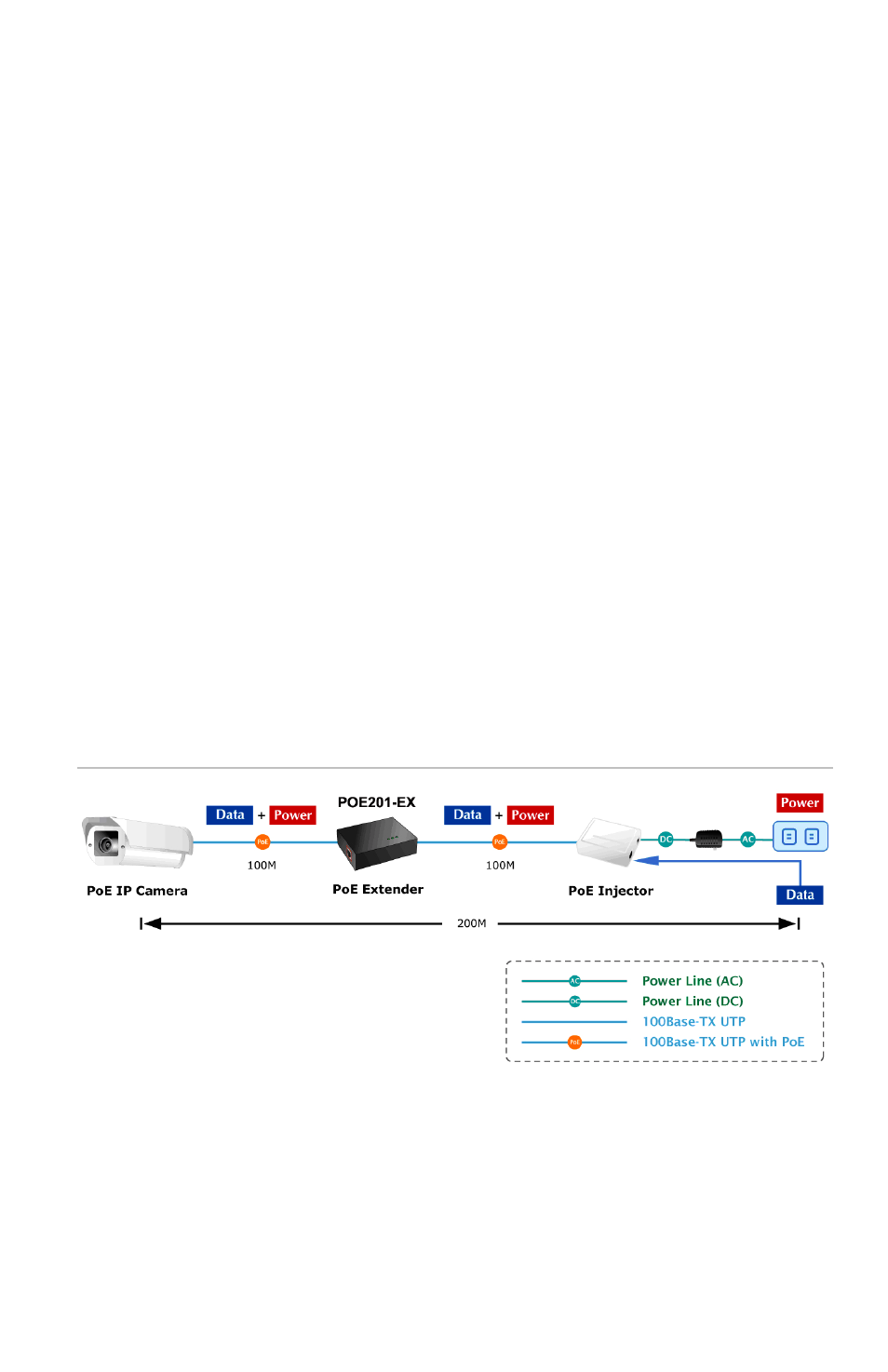
Powered Device (PD) Installation
1. Connect one side of the CAT5e/6 cable to the "OUT" port
of the POE201-EX, and the other side to the PD.
2. The "OUT" port injects power and transfers data to the PD.
3. Once the PD is detected, the “PoE OUT” LED indicator will
illuminate in a steady state showing that it is providing
power.
Figure 2: Extender connection diagram
Note:
The POE201-EX will not inject power to a PD that
doesn't comply to the IEEE 802.3af standard. Therefore, in this
type of connection, the PoE Out LED will not illuminate.
- 600-1053-4 (12 pages)
- NX-590NE (38 pages)
- NX-591NE-GSM (16 pages)
- NX-592E (13 pages)
- Simon XT CDMA Module V4 (9 pages)
- Simon XT GSM Module V4 (10 pages)
- NX-548E (12 pages)
- NX-540E (32 pages)
- D1000 Series (10 pages)
- D1300 Series (11 pages)
- D1315 Series (10 pages)
- D1810 Series (8 pages)
- D2100 Series (10 pages)
- D2300CPS Series (10 pages)
- D7100 Series (8 pages)
- D7400 Series (10 pages)
- D7400RSH Series (10 pages)
- DE7100 Series (9 pages)
- DE7200M Series (8 pages)
- DE7300 Series (9 pages)
- DECT3000 Series (8 pages)
- DED2500 Series (9 pages)
- DT3000 Series (6 pages)
- D1200 Series (8 pages)
- D19100SHR Series (16 pages)
- D9100 Series (12 pages)
- MC250-4T/1CXT (25 pages)
- MC251-4P/1CXT (28 pages)
- MC250-4T Series (23 pages)
- MC251-4P/1S (27 pages)
- MC350-4T-2S (32 pages)
- MC352-4P-2S (31 pages)
- MCR200-1T/1CX (25 pages)
- MCR200-1T-1TW (23 pages)
- MC250-1T/1S (24 pages)
- MCR205-1T/1S User Manual (62 pages)
- MCR205-1T/1S Installation Guide (11 pages)
- MC201-1P/1FS (20 pages)
- MC355-1T/1S Installation Guide (13 pages)
- MC350-1T-2S (29 pages)
- MC352-1P/1S (29 pages)
- MC355-1T/1S User Manual (64 pages)
- MCR300-1T/1S (20 pages)
- MCR300-1T-2S (17 pages)
- MCR-R15 (14 pages)