5 wiring the fault alarm contact – Interlogix MC350-4T-2S User Manual
Page 14
14
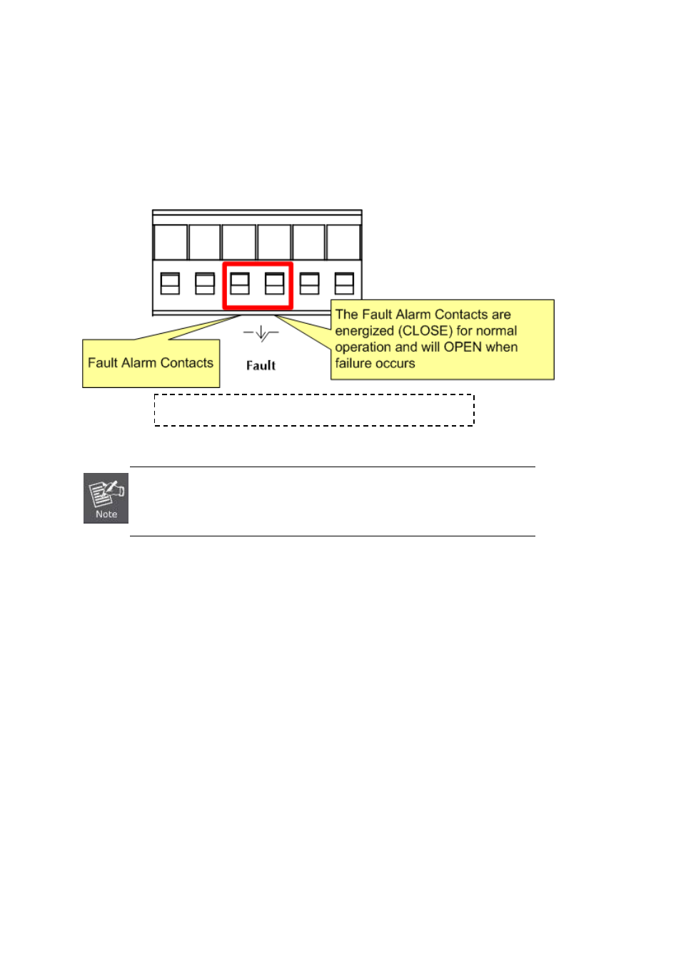
2.1.5 Wiring the Fault Alarm Contact
The fault alarm contacts are in the middle of the terminal block connector as the picture shows below. Inserting the wires,
the Industrial Gigabit Ethernet Switch will detect the fault status of the power failure and then forms an open circuit. The
following illustration shows an application example for wiring the fault alarm contacts.
1 2 3 4 5 6
The wire gauge for the terminal block should be in the range between 12 and 24 AWG.
Insert the wires into the fault alarm contacts
See also other documents in the category Interlogix Accessories communication:
- 600-1053-4 (12 pages)
- NX-590NE (38 pages)
- NX-591NE-GSM (16 pages)
- NX-592E (13 pages)
- Simon XT CDMA Module V4 (9 pages)
- Simon XT GSM Module V4 (10 pages)
- NX-548E (12 pages)
- NX-540E (32 pages)
- D1000 Series (10 pages)
- D1300 Series (11 pages)
- D1315 Series (10 pages)
- D1810 Series (8 pages)
- D2100 Series (10 pages)
- D2300CPS Series (10 pages)
- D7100 Series (8 pages)
- D7400 Series (10 pages)
- D7400RSH Series (10 pages)
- DE7100 Series (9 pages)
- DE7200M Series (8 pages)
- DE7300 Series (9 pages)
- DECT3000 Series (8 pages)
- DED2500 Series (9 pages)
- DT3000 Series (6 pages)
- D1200 Series (8 pages)
- D19100SHR Series (16 pages)
- D9100 Series (12 pages)
- MC250-4T/1CXT (25 pages)
- MC251-4P/1CXT (28 pages)
- MC250-4T Series (23 pages)
- MC251-4P/1S (27 pages)
- MC352-4P-2S (31 pages)
- MCR200-1T/1CX (25 pages)
- MCR200-1T-1TW (23 pages)
- MC250-1T/1S (24 pages)
- MCR205-1T/1S User Manual (62 pages)
- MCR205-1T/1S Installation Guide (11 pages)
- MC201-1P/1FS (20 pages)
- MC355-1T/1S Installation Guide (13 pages)
- MC350-1T-2S (29 pages)
- MC352-1P/1S (29 pages)
- MC355-1T/1S User Manual (64 pages)
- MCR300-1T/1S (20 pages)
- MCR300-1T-2S (17 pages)
- MCR-R15 (14 pages)