3 bidirectional talk, 4 alarm setup – IC Realtime 3.0 MegaPixel 8-16mm VF IP66 IP Bullet/Box Camera with IR & POE (ICIPS3000AF) User Manual
Page 7
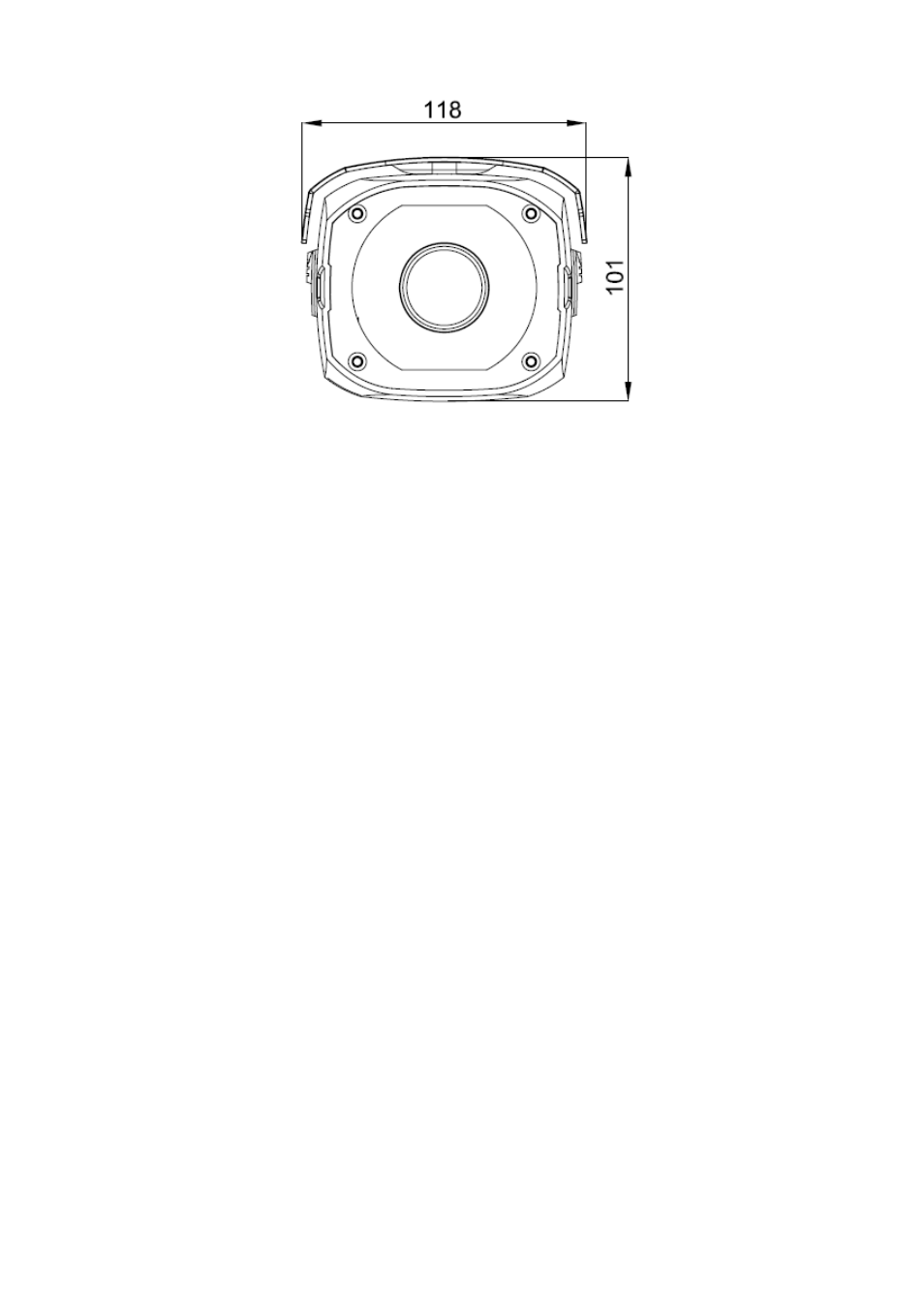
3
Figure 1-3
1.3 Bidirectional talk
1.3.1 Device-end to PC-end
Device Connection
Please connect the speaker or the pickup to the first audio input port in the device rear panel.
Then connect the earphone or the sound box to the audio output port in the PC.
Login the Web and then enable the corresponding channel real-time monitor.
Listening Operation
At the device end, speak via the speaker or the pickup, and then you can get the audio from the
earphone or sound box at the pc-end.
1.3.2 PC-end to the device-end
Device Connection
Connect the speaker or the pickup to the audio output port in the PC and then connect the
earphone or the sound box to the first audio input port in the device rear panel.
Login the Web and then enable the corresponding channel real-time monitor.
Listening Operation
At the PC-end, speak via the speaker or the pickup, and then you can get the audio from the
earphone or sound box at the device-end.
1.4 Alarm Setup
The alarm interface is shown as in Figure 1-4. Please follow the steps listed below for local alarm
input and output connection.
1) Connect the alarm input device to the alarm input port (No.3 pin or No.4 pin) of the I/O cable.
2) Connect the alarm output device to the alarm output port (No.2 pin) and alarm output public
port (No.1 pin). The alarm output port supports NO (normal open) alarm device only.
3) Open the Web, go to the Figure 1-4. Please set the alarm input 01 port for the first channel of
the I/O cable (No.3 pin). The alarm input 02 is for the 2
nd
channel of I/O cable (No.4 pin). Then
you can select the corresponding type (NO/NC.)