Connection sample, Network system, 3 connection sample – IC Realtime 1/2/4 Channel H.264 Network Video Server User Manual
Page 18
12
Port Name
Connector
Function
1~4
Alarm Input Port
1~4
I/O Port
Alarm input channel amount is 4
When your alarm input device is using
external power, please make sure the
device and the NVS have the same
ground.
Ground end
Alarm input ground end.
NO
Alarm Output
Port1
Output alarm signal to the alarm device.
Please make sure there is power to the
external alarm device.
NO:Normal open alarm output port.
C:Alarm output public end.
C
A
RS485 Port
RS485_A port. It is the cable A. You can
connect to the control devices such as speed
dome PTZ.
B
RS485_B.It is the cable B. You can connect
to the control devices such as speed dome
PTZ.
ANT
Antenna Port
To connect wireless antenna in order to
receive 3G wireless signal
Power input port
Input 12V DC
Power Button
Power on/off button.
When connect the Ethernet port, please use crossover cable to connect the PC and use the
straight cable to connect to the switcher or router.
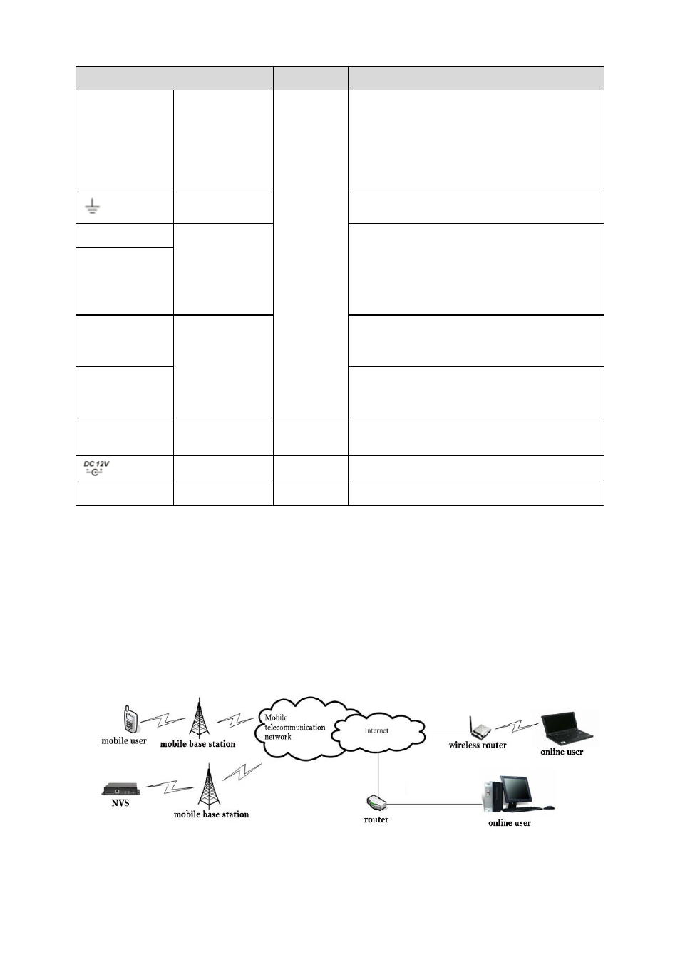
2.3 Connection Sample
The connection sample is shown as below..
The following figure is based on the 4-channel series product of SD backup series and HDD
backup series respectively.
2.3.1 Network system
Figure 2-6