Haltech HT055045 User Manual
Page 15
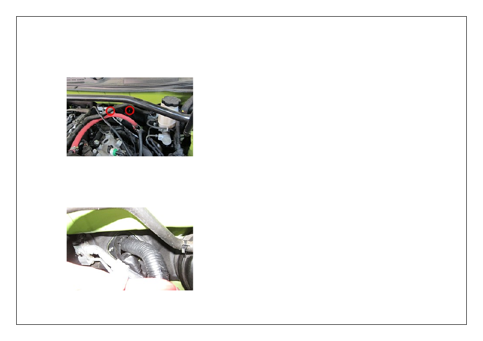
5.
Remove the two firewall mounted nuts that secure the plastic cover over the top of the
wiring harness firewall pass through grommet, once the nuts are removed from the
plastic cover it can be removed to access the pass through grommet.
Removing the plastic cover can be difficult as there is a metal ring that sits inside the
plastic cover and clamps the rubber grommet underneath in place.
The cover is easier to remove with the metal ring remaining seated on the firewall
(ie don’t let the ring come out with the cover, it may be beneficial to remove the brake
booster vacuum hose for easier access).
Figure 5 – Factory Grommet Location
6.
With the plastic cover removed you should be able to access the rubber grommet that
the wiring harness passes through into the cabin, remove the metal ring,
cut the grommet and route the wiring harness through into the passenger compartment.
Figure 6 – Factory Grommet
Digital Pulsed Input ( DPI )
Digital Pulsed Inputs are capable of accepting pulsed input information such as for a
road speed sensor. These inputs measure the time periods between the pulses and
can process this information to provide quantities such as road speed.
One additional input can be connected using the Optional Rear Auxiliary
Harness ( HT040003 )
Digital Pulsed Outputs ( DPO )
Digital Pulsed Outputs are capable of producing pulsed waveforms with varying duty
and frequency. DPO's can be used to control various devices such as thermo-fans,
shift lights, bypass air control valves, boost control solenoids etc.
When a Digital Pulsed output is activated by the ECU the output will switch to ground.
Solenoid valves and shift lights etc can be run directly from the output, however
high current devices such as thermo-fans and additional fuel pumps must be activated
through a relay. This way the DPO is only switching a relay and not a high current
draw device.
Two additional outputs can be connected using the Optional Rear Auxiliary
Harness ( HT040003 )
Digital Pulsed Outputs are limited to 800mA Max current draw.
Digital Switched Outputs ( DSO )
Digital Switched Outputs are capable of switching to ground
DSO's can be used to control relays in an on / off state only.
Two additional outputs can be connected using the Optional Rear Auxiliary
Harness ( HT040003 )
Digital Switched Outputs are limited to 800mA Max current draw.
Analogue Voltage Inputs ( AVI )
Analogue Voltage Inputs accept variable voltage inputs from 0V to 5V. These inputs
can also accept switch inputs that change between two different voltage levels.
The On Voltage and Off Voltage define what the thresholds are between the On and Off
states. The Voltage can be viewed as a channel in the software to determine the
thresholds for a switched input.
Two additional sensors or switched inputs can be connected using the
Optional Rear Auxiliary Harness ( HT040003 )
Wire connections
When using crimp connectors ensure that the correct crimping tool is used – if in
doubt do a pull test on a crimp connector, the wire should break before the wire
pulls out of the crimp. Terminal soldering can weaken a connection and should only
be used as a last resort. If solder joints are used, ensure joints are well isolated
from movement as solder joints are prone to fracture.
When splicing 2 wires it is preferable to use a crimp splice – again if using a solder
joint, ensure joint is limited in its range of possible movement as solder joints are
prone to fracture. Always use heat-shrink sleeving to insulate wires.